


25
COMMISSIONING MANUAL
POWERDRIVE MD
Variable speed drive
PARAMETER SETTING INTERFACE
LEROY-SOMER
3871 en - 2011.05 / h
: Motor rated volta
g
e
Adjustment range : 0 to 999 V
Factory setting
:
Eur: 400 V
, USA: 460 V
Enter the rated voltage shown on the nameplate taking
account of the normal power supply conditions.
: Rated power factor
Adjustment range : 0 to 1.00
Factory setting
: 0.85
The power factor is measured automatically during a level 2
autotune phase (see
00.42
) and set in this parameter.
If it has not been possible to carry out the autotune procedure,
enter the Cos
M
value indicated on the motor nameplate.
: Motor rated fre
q
uency
Adjustment range : 0 to 999.9 Hz
Factory setting
:
Eur = 50.0 Hz
: USA = 60.0 Hz
This is the point at which motor operation changes from
constant torque to constant power.
In standard operation, it is the frequency indicated on the
motor nameplate.
: Number of motor poles
Adjustment range : Auto (0), 2 Poles (1), 4 Poles (2),
6 Poles (3), 8 Poles (4), 10 Poles (5),
12 Poles (6), 14 Poles (7), 16 Poles (8)
Factory setting
: Auto (0)
When this parameter is at 0 (Automatic), the drive
automatically calculates the number of poles according to the
rated speed (
00.07
) and the rated frequency (
00.10
).
However, the value can be entered directly
in accordance with the table below:
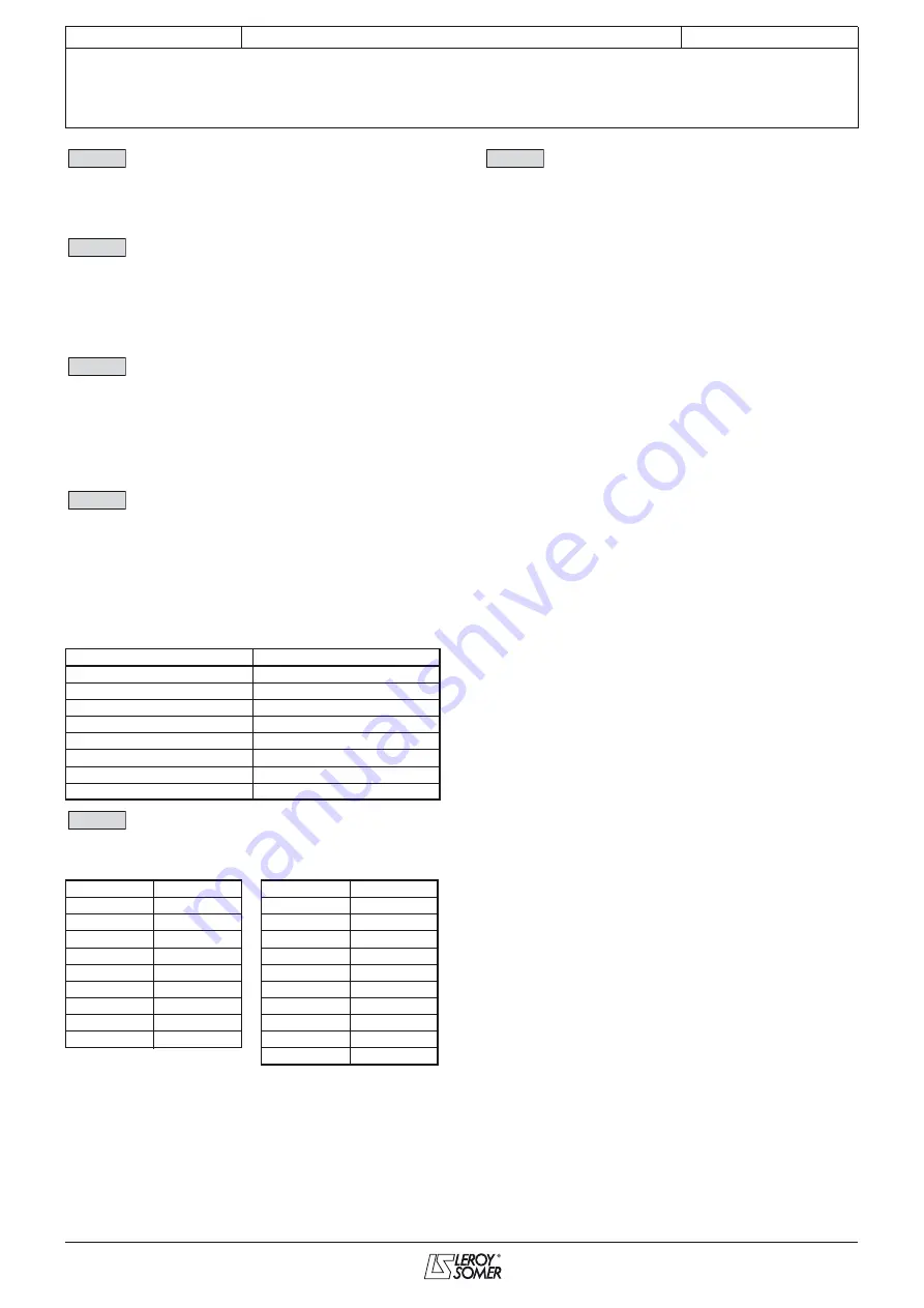
: Maximum switchin
g
fre
q
uency
Adjustment range : 1,5 kHz to 14 kHz (see table below)
Factory setting
: 3 kHz (2)
Sets the PWM switching frequency.
Note :
For frequencies higher than 6kHz, phase contact
LEROY-SOMER.
CAUTION:
A hi
g
h switchin
g
fre
q
uency reduces the ma
g
netic noise,
however it increases the drive temperature rise.
Refer to the installation manual to determine the deratin
g
of the drive accordin
g
to the fre
q
uency.
: User drive mode
Adjustment range : OPEN LOOP (0),
OPEN LOOP (1),
CL LP Vector (2),
SERVO (3),
REGEN (4),
Syn VS REGEN (5),
Asy VS REGEN (6)
Conv DC/DC (7)
Factory setting
: OPEN LOOP (0)
The choice of operating mode can only be made
when the drive is stopped.
OPEN LOOP (0 and 1): Asynchronous motor controlled in
open loop mode (see also parameter
00.14
).
CL LP Vector (2):
Asynchronous motor controlled in closed
loop mode
(see also parameter
00.14
).
SERVO (3):
Servo or synchronous motor controlled in closed
loop mode (see also parameter
00.14
).
REGEN (4):
Reversible mode.
Syn VS REGEN (5):
Reversible mode with variable speed
synchronous generator.
Asy VS REGEN (6):
Reversible mode with variable speed
asynchronous generator.
Conv DC/DC (7):
Get in touch with your usual
LEROY-SOMER contact.
Note:
A change from open loop mode (
00.13
= OPEN LOOP
(0 or 1) to closed loop mode (
00.13
= CL LP Vector (2) or
SERVO (3)), or vice versa, causes a return to factory settings
of parameters
12.45
Brake apply frequency or speed
threshold, and
12.46
Magnetisation time delay/speed
threshold.
CAUTION:
If the mode is chan
g
ed with a fieldbus option, reset the
option (Pr
15.32
= ON).
Number of poles
00.11
2
1
4
2
6
3
8
4
10
5
12
6
14
7
16
8
Fre
q
uency
00.12
Fre
q
uency
00.12
2 kHz
0
6.5 kHz
9
2.5 kHz
1
7 kHz
10
3 kHz
2
8 kHz
11
3.5 kHz
3
9 kHz
12
4 kHz
4
10 kHz
13
4.5 kHz
5
11 kHz
14
5 kHz
6
12 kHz
15
5.5 kHz
7
13 kHz
16
6 kHz
8
14 kHz
17
1,5 kHz
18
00.08
00.09
00.10
00.11
00.12
00.13