


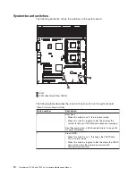


System-board switches
The following illustration shows the switches on the system board.
1
2
3
4
5
6
7
8
9
10
11
12
DIMM LEDs
1
SW3
2
SW4 (Boot block/Clear CMOS)
The following table describes the function of each switch on the system board.
Table 2. System board switches
Switch number
Description
1
Boot block:
v
When this switch is on
1
, this is normal mode.
v
When this switch is toggled to
On
, this enables the
system to recover if the BIOS code becomes damaged.
See “Recovering from a BIOS update failure” on page 203
for more information.
2
Clear CMOS:
v
When this switch is on 2, this keeps the CMOS data.
This is normal mode.
v
When this switch is toggled to
On
, this clears the CMOS
data, which clears the power-on password and
administrator password.
14
ThinkServer TD100 and TD100x: Hardware Maintenance Manual
Summary of Contents for ThinkServer TD100
Page 2: ......
Page 18: ...xvi ThinkServer TD100 and TD100x Hardware Maintenance Manual ...
Page 42: ...24 ThinkServer TD100 and TD100x Hardware Maintenance Manual ...
Page 238: ...220 ThinkServer TD100 and TD100x Hardware Maintenance Manual ...
Page 253: ......
Page 254: ...Part Number 46U0860 Printed in USA 1P P N 46U0860 ...