


14. Replace any adapters that you removed (see “Installing an adapter” on page
82); then, install the side cover (see “Installing the side cover” on page 79).
15. Lock the side cover if it was unlocked during removal.
16. Reconnect the external cables and power cords; then, turn on the attached
devices and turn on the server.
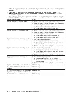
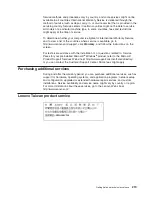
The following table describes the function of each switch on the system board.
Table 17. System board switches
Switch number
Description
1
Boot block:
v
When this switch is on 1, this is normal mode.
v
When this switch is toggled to
On
, this enables the
system to recover if the BIOS code becomes damaged.
2
Clear CMOS:
v
When this switch is on
2
, this is normal mode. This
keeps the CMOS data.
v
When this switch is toggled to
On
, this clears the CMOS
data, which clears the power-on password and
administrator password.
204
ThinkServer TD100 and TD100x: Hardware Maintenance Manual
Summary of Contents for ThinkServer TD100
Page 2: ......
Page 18: ...xvi ThinkServer TD100 and TD100x Hardware Maintenance Manual ...
Page 42: ...24 ThinkServer TD100 and TD100x Hardware Maintenance Manual ...
Page 238: ...220 ThinkServer TD100 and TD100x Hardware Maintenance Manual ...
Page 253: ......
Page 254: ...Part Number 46U0860 Printed in USA 1P P N 46U0860 ...