

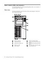
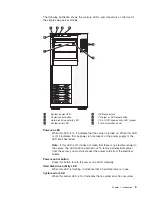


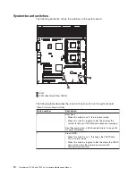


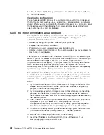


Internal connectors, LEDs, and switches
The following illustrations show the connectors, light-emitting diodes (LEDs), and
switches on the system board. The illustrations might differ slightly from your
hardware.
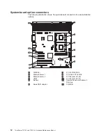
System-board internal connectors
The following illustration shows the internal connectors on the system board.
1
2
3
4
5
6
7
8
9
10
11
12
DIMM LEDs
1
Main power
10
SAS/SATA backplane power
2
Power
11
Simple-swap SATA backplate
3
Power
12
Hot-swap SAS/SATA signal
4
USB tape
13
Hot-swap main fan
5
Front panel
14
Hot-swap fan (redundant)
6
Primary IDE
15
Battery
7
Front USB
16
Wake on LAN
8
Microprocessor 1
17
COM 2 header
9
Microprocessor 2
18
Rear fan
10
ThinkServer TD100 and TD100x: Hardware Maintenance Manual
Summary of Contents for ThinkServer TD100
Page 2: ......
Page 18: ...xvi ThinkServer TD100 and TD100x Hardware Maintenance Manual ...
Page 42: ...24 ThinkServer TD100 and TD100x Hardware Maintenance Manual ...
Page 238: ...220 ThinkServer TD100 and TD100x Hardware Maintenance Manual ...
Page 253: ......
Page 254: ...Part Number 46U0860 Printed in USA 1P P N 46U0860 ...