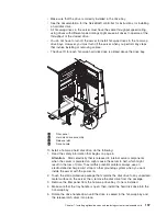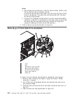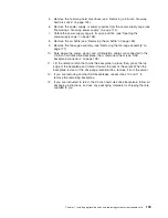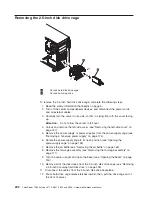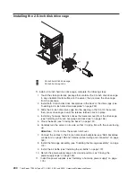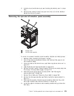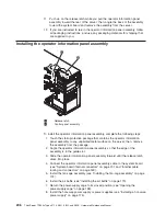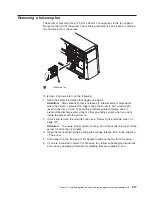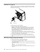
9. Close the bezel (see “Closing the bezel” on page 151).
10. Install and lock the left-side cover (see “Installing the left-side cover” on page
158).
11. Reconnect the external cables and power cords; then, turn on the attached
devices and turn on the server.
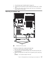
Removing an extender card
1
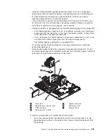
Extender card retaining screws
To remove an extender card, complete the following steps:
1. Read the safety information that begins on page 5.
2. Turn off the server and all attached devices; then, disconnect all power cords
and external cables.
3. Carefully turn the server on its side so that it is lying flat, with the cover facing
up.
Attention:
Do not allow the server to fall over.
Chapter 7. Installing optional devices and replacing customer replaceable units
207
Summary of Contents for THINKSERVER 3719
Page 1: ...ThinkServer TD200x Machine Types 3719 3821 3822 and 3823 Hardware Maintenance Manual ...
Page 2: ......
Page 3: ...ThinkServer TD200x Types 3719 3821 3822 and 3823 Hardware Maintenance Manual ...
Page 12: ...4 ThinkServer TD200x Types 3719 3821 3822 and 3823 Hardware Maintenance Manual ...
Page 22: ...14 ThinkServer TD200x Types 3719 3821 3822 and 3823 Hardware Maintenance Manual ...
Page 28: ...20 ThinkServer TD200x Types 3719 3821 3822 and 3823 Hardware Maintenance Manual ...
Page 34: ...26 ThinkServer TD200x Types 3719 3821 3822 and 3823 Hardware Maintenance Manual ...
Page 244: ...236 ThinkServer TD200x Types 3719 3821 3822 and 3823 Hardware Maintenance Manual ...
Page 258: ...250 ThinkServer TD200x Types 3719 3821 3822 and 3823 Hardware Maintenance Manual ...
Page 282: ...274 ThinkServer TD200x Types 3719 3821 3822 and 3823 Hardware Maintenance Manual ...
Page 286: ...278 ThinkServer TD200x Types 3719 3821 3822 and 3823 Hardware Maintenance Manual ...
Page 296: ...288 ThinkServer TD200x Types 3719 3821 3822 and 3823 Hardware Maintenance Manual ...
Page 303: ......
Page 304: ...Part Number XXXXXX Printed in USA 1P P N XXXXXX ...


