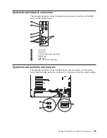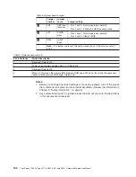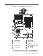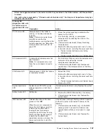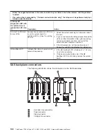
Chapter 6. Locating Server Controls and connectors
This section describes the controls and light-emitting diodes (LEDs) and how to turn
the server on and off.
Front view
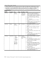
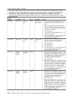
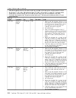
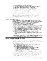
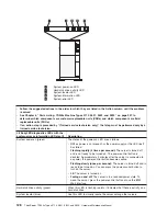
The following illustration shows the controls and LEDs on the front of the server.
Note:
The front bezel door is not shown so that the drive bays are visible.
1
DVD drive activity LED (green)
7
System-error LED
2
System-power LED
8
USB 2
3
Power-control button
9
USB 1
4
Hard-disk drive activity LED
10
DVD drive eject button
5
System-locator LED
11
Hard disk drive status LED
(amber)
6
System-information LED
12
Hard disk drive activity LED
(green)
Operator information panel
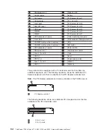
The following illustration shows the LEDs on the operator information panel on the
front of the server.
© Lenovo 2009. Portions © IBM Corp. 2009.
127
Summary of Contents for THINKSERVER 3719
Page 1: ...ThinkServer TD200x Machine Types 3719 3821 3822 and 3823 Hardware Maintenance Manual ...
Page 2: ......
Page 3: ...ThinkServer TD200x Types 3719 3821 3822 and 3823 Hardware Maintenance Manual ...
Page 12: ...4 ThinkServer TD200x Types 3719 3821 3822 and 3823 Hardware Maintenance Manual ...
Page 22: ...14 ThinkServer TD200x Types 3719 3821 3822 and 3823 Hardware Maintenance Manual ...
Page 28: ...20 ThinkServer TD200x Types 3719 3821 3822 and 3823 Hardware Maintenance Manual ...
Page 34: ...26 ThinkServer TD200x Types 3719 3821 3822 and 3823 Hardware Maintenance Manual ...
Page 244: ...236 ThinkServer TD200x Types 3719 3821 3822 and 3823 Hardware Maintenance Manual ...
Page 258: ...250 ThinkServer TD200x Types 3719 3821 3822 and 3823 Hardware Maintenance Manual ...
Page 282: ...274 ThinkServer TD200x Types 3719 3821 3822 and 3823 Hardware Maintenance Manual ...
Page 286: ...278 ThinkServer TD200x Types 3719 3821 3822 and 3823 Hardware Maintenance Manual ...
Page 296: ...288 ThinkServer TD200x Types 3719 3821 3822 and 3823 Hardware Maintenance Manual ...
Page 303: ......
Page 304: ...Part Number XXXXXX Printed in USA 1P P N XXXXXX ...


