System-board LEDs
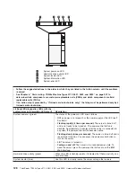
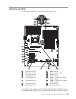
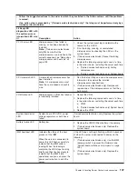
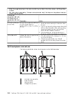
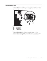
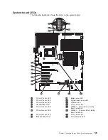
The following illustration shows the LEDs on the system board.
1
PCI slot 1 error LED
9
Battery error LED
2
PCI slot 2 error LED
10
System-board error LED
3
PCI slot 3 error LED
11
VRM fail LED
4
HS heartbeat LED
12
CPU 1 error LED
5
PCI slot 4 error LED
13
DIMMs 1 - 8 error LEDs (starting
from the bottom)
6
PCI slot 5 error LED
14
DIMMs 9 - 16 error LEDs (starting
from the bottom)
7
PCI slot 6 error LED
15
CPU 2 error LED
8
IMM heartbeat LED
16
CPU mismatch LED
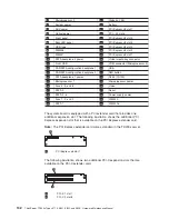
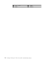
The system board is equipped with a PCI extender card that provides either one or
two additional expansion slots. The following illustration shows the LEDs on the PCI
Chapter 6. Locating Server Controls and connectors
135
Summary of Contents for THINKSERVER 3719
Page 1: ...ThinkServer TD200x Machine Types 3719 3821 3822 and 3823 Hardware Maintenance Manual ...
Page 2: ......
Page 3: ...ThinkServer TD200x Types 3719 3821 3822 and 3823 Hardware Maintenance Manual ...
Page 12: ...4 ThinkServer TD200x Types 3719 3821 3822 and 3823 Hardware Maintenance Manual ...
Page 22: ...14 ThinkServer TD200x Types 3719 3821 3822 and 3823 Hardware Maintenance Manual ...
Page 28: ...20 ThinkServer TD200x Types 3719 3821 3822 and 3823 Hardware Maintenance Manual ...
Page 34: ...26 ThinkServer TD200x Types 3719 3821 3822 and 3823 Hardware Maintenance Manual ...
Page 244: ...236 ThinkServer TD200x Types 3719 3821 3822 and 3823 Hardware Maintenance Manual ...
Page 258: ...250 ThinkServer TD200x Types 3719 3821 3822 and 3823 Hardware Maintenance Manual ...
Page 282: ...274 ThinkServer TD200x Types 3719 3821 3822 and 3823 Hardware Maintenance Manual ...
Page 286: ...278 ThinkServer TD200x Types 3719 3821 3822 and 3823 Hardware Maintenance Manual ...
Page 296: ...288 ThinkServer TD200x Types 3719 3821 3822 and 3823 Hardware Maintenance Manual ...
Page 303: ......
Page 304: ...Part Number XXXXXX Printed in USA 1P P N XXXXXX ...


