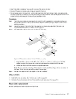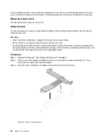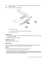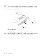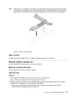
Step 4. Position the riser assembly on the chassis. Align the plastic clip and two pins on the bracket with
the guide pin and two holes on the chassis and align the riser card with the riser slot on the system
board. Then, carefully press the riser assembly straight down into the slot until it is fully seated.
Figure 58. Riser assembly installation
After you finish
Complete the parts replacement. See “Complete the parts replacement” on page 113.
Memory module replacement
Use this information to remove and install a memory module.
Remove a memory module
Use this information to remove a memory module.
About this task
Attention:
• Read “Installation Guidelines” on page 25 to ensure that you work safely.
• Power off the server and disconnect all power cords for this task.
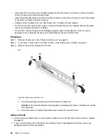
• Memory modules are sensitive to static discharge and require special handling. Refer to the standard
guidelines for “Handling static-sensitive devices” on page 26.
– Always wear an electrostatic-discharge strap when removing or installing memory modules.
Electrostatic-discharge gloves can also be used.
.
Hardware replacement procedures
85
Summary of Contents for HR650X V2
Page 1: ...HR650X V2 User Guide Machine Types 7D4D ...
Page 8: ......
Page 14: ...6 HR650X V2 User Guide ...
Page 30: ...22 HR650X V2 User Guide ...
Page 122: ...114 HR650X V2 User Guide ...
Page 152: ...144 HR650X V2 User Guide ...
Page 176: ...168 HR650X V2 User Guide ...
Page 182: ...174 HR650X V2 User Guide ...
Page 186: ...178 HR650X V2 User Guide ...
Page 190: ...182 HR650X V2 User Guide ...
Page 191: ......
Page 192: ......


