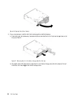
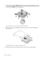

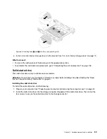
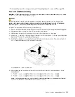

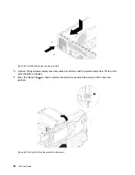
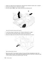
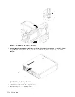

Figure 77. Screws that secure the heat sink and fan assembly
7. Lift the failing heat sink and fan assembly off the system board.
Notes:
• You might have to twist the heat sink and fan assembly gently to free it from the microprocessor.
• Do not touch the thermal grease while handling the heat sink and fan assembly.
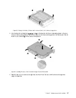
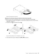
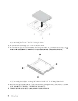
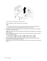
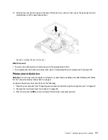
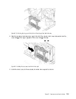
8. Position the new heat sink and fan assembly on the system board so that the four screws are aligned
with the holes in the system board.
Note:
Ensure that the heat sink and fan assembly cable is toward the microprocessor fan connector on
the system board.
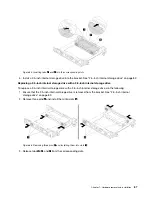
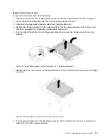
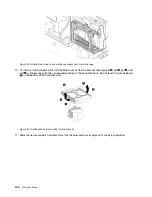
9. Follow the following sequence to install the four screws to secure the new heat sink and fan assembly.
Do not over-tighten the screws.
a. Partially tighten screw
1
, then fully tighten screw
2
, and then fully tighten screw
1
.
b. Partially tighten screw
3
, then fully tighten screw
4
, and then fully tighten screw
3
.
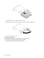
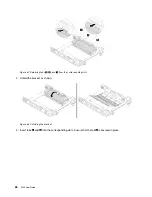
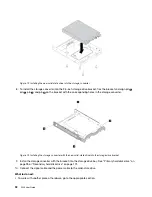
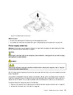
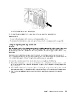
10. Connect the heat sink and fan assembly cable to the microprocessor fan connector on the system
board. See “Parts on the system board” on page 6.
11. Lower and position the heat sink fan duct on the top of the heat sink and fan assembly until it snaps into
position.
94
P320 User Guide
Summary of Contents for 30BG
Page 1: ...P320 User Guide Machine Types 30BJ 30BK and 30BS ...
Page 12: ...x P320 User Guide ...
Page 28: ...16 P320 User Guide ...
Page 40: ...28 P320 User Guide ...
Page 46: ...34 P320 User Guide ...
Page 56: ...44 P320 User Guide ...
Page 120: ...108 P320 User Guide ...
Page 124: ...112 P320 User Guide ...
Page 126: ...114 P320 User Guide ...
Page 128: ...116 P320 User Guide ...
Page 136: ...124 P320 User Guide ...
Page 140: ...4 Follow the instructions on the screen 128 P320 User Guide ...
Page 142: ...130 P320 User Guide ...
Page 144: ...132 P320 User Guide ...
Page 145: ......
Page 146: ......