Page 210
Job editor
Group 8
Release R1.12 en
JET2 neo
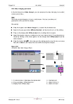
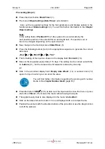
1
– Both sensors at the same height
6
– Input field <Sensor distance>
2
– Distance between sensors <A>
7
– Sensor 1 – Start measurement –
Connected to
X5.5.
3
– Maximum <Sensor distance>
8
– Sensor 2 – Stop measurement –
Connected to
X5.4
. This sensors
works also as PrintGo sensor
4
– The Distance A (between the 2 sensors)
has to be smaller than Distance B
(between the products)
9
– Input field <intern Speed>
5
– Wrong setup – more than one product
between the 2 sensors
Speed measuring with two sensors - Continuation
Description of the functionality
The two sensors have to be mounted on the production line in a way that they can be
activated by the products passing by. For this the two sensors have to be mounted on the
same height
(1)
and at a certain distance from each other
(2)
.
As higher the production (line) speed as larger should be the sensor distance.
The maximum distance allowed is
250 mm
(3)
.
The distance between the two sensors has to be smaller than the distance between two
products
(4)
.
As a rule of thumb there must be never more than one product between the 2 sensors!
(5)
The actual distance has to be measured and entered in the corresponding input field
(6)
.
This input field is located on the tab <Encoder> in the dialogbox <Print parameter>
6
9
A
Summary of Contents for JET2 neo
Page 1: ...Manual LEIBINGER JET2NEO Release 1 12en ...
Page 2: ......
Page 11: ...Group 1 Table of contents Page 9 JET2 neo Release R1 12 en ...
Page 12: ......
Page 21: ...Group 2 Safety Page 19 JET2 neo Release R1 12 en 2 4 Safety sticker Figure 1 Safety sticker ...
Page 276: ...Page 274 Appendix Group 12 Release R1 12 en JET2 neo Interface X4 Inputs Interface X3 Outputs ...


