


139
13. STATUS DISPLAY
STATUS → F•4 ANC PACKET → F•3 V-ANC ARIB → F•2 NET-Q
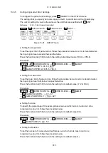
13.5.5
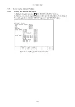
Displaying the Inter-Stationary Control Signal
When the input signal is SD or HD, to display the content of the inter-stationary control signal
defined in the ARIB standard, follow the procedure below.
You can set the display format to text or dump format.
Procedure
Figure 13-13 Displaying the inter-stationary control signal
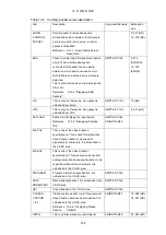
Table 13-9 Displaying the inter-stationary control signal
Item
Description
LINE NUMBER
Displays the line number that the inter-stationary control signal is
embedded in.
ERROR CORRECTION
Displays the presence of error correction.
CONTINUITY INDEX
Displays a counter that shows packet continuity.
STATION CODE
Displays the station code using the alphabet or katakana.
DATE & TIME
Displays the originating station date and time.
VIDEO CURRENT
Displays the current video mode.
AUDIO CURRENT
Displays the current audio mode.
DOWN MIX CURRENT
Displays the current audio down mix setting.
NEXT
Displays the next video mode, audio mode, audio down mix setting.
COUNTDOWN
Displays a countdown of the video mode and audio mode switching.
TRIGGER SIGNAL
Displays the trigger signal, which indicates the timing.
COUNTER
Displays the counter for TRIGGER SIGNAL Q1 to Q4.
COUNTDOWN
Displays the timing information for TRIGGER SIGNAL Q1 to Q4.
STATUS SIGNAL
Displays the status signal.