


44
4
Design and Functions
Before working on the flame detector, switch off the power supply. Before first commissioning
or replacement of the device, check external wiring!
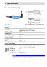
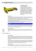
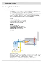
Mounting Instructions
The KLC 20/KLC 2002 should be mounted close to the flame with straight alignment using the
Mounting Flange KLC or another suitable holder with Ø0.551 inch (14 mm) opening. Mount
the detector with a holder. The best flame signal will be achieved from strong flickering parts
of the flame radiation. The angle of view, especially with sight tubes, must be of appropriate
dimensions to avoid any reduction of flame radiation. Protect the sensor from other light sourc-
es.
NOTICE
To avoid any disturbance, do not align the detector direct to the ignition spark. Breakdowns
during pre-purge procedure may occur.
The maximum length of the connection must be in accordance with the technical data. Install
the detector connection cable with most possible distance to the ignition cable or the mains
cable. Avoid to lay the connecting cable in parallel to these cables.
CAUTION!
Due to safety and technical regulations, a control shut down must be done at least once
every 24 hours.
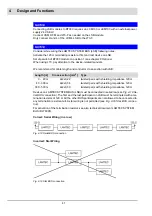
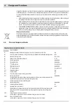
Operating Indicator LED
Via the built-in LED the flame detector KLC 20/KLC 2002 is indicating the following operating
conditions:
LED is OFF
KLC is not active.
LED is blinking
KLC is active, safety test finished, no flame detected
LED is ON
KLC is active, safety test finished, flame detected
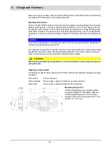
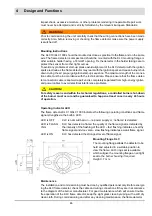
Mounting Flange KLC
The Mounting Flange KLC provides attach-
ment and adjustment of the flame detector.
The Mounting Flange KLC can be simply
sealed to the burner housing using an o-ring.
Height = 0.3 in (7 mm).
Summary of Contents for BT300 BurnerTronic
Page 2: ......
Page 25: ...24 3 Product Description Fig 3 9 Temperature derating BT300 for operation 2000 m NHN...
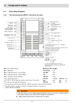
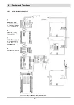
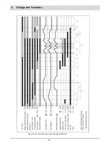
Page 49: ...48 4 Design and Functions Fig 4 20 Oil with pilot burner BT300...
Page 50: ...49 4 Design and Functions Fig 4 21 Oil without pilot burner BT300...
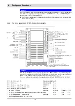
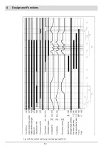
Page 51: ...50 4 Design and Functions Fig 4 22 Gas with pilot burner and leakage test BT300...
Page 52: ...51 4 Design and Functions Fig 4 23 Gas without pilot burner and leakage test BT300...
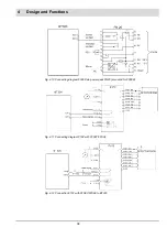
Page 53: ...52 4 Design and Functions Fig 4 24 Oil without pilot burner BT335...
Page 54: ...53 4 Design and Functions Fig 4 25 Gas without pilot burner and leakage test BT335...
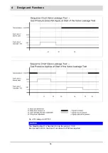
Page 59: ...58 4 Design and Functions Fig 4 28 Leakage test process diagram...
Page 98: ...97 6 Operating Control and Displays...
Page 99: ...98 6 Operating Control and Displays...
Page 103: ...102 6 Operating Control and Displays...
Page 105: ...104 6 Operating Control and Displays...
Page 106: ...105 6 Operating Control and Displays...
Page 107: ...106 6 Operating Control and Displays...
Page 109: ...108 6 Operating Control and Displays...
Page 126: ...125 6 Operating Control and Displays 6 3 4 2 Curve Table Fig 6 37 Curve table window...
Page 246: ...242 10 EU Declaration of Conformity 10 EU Declaration of Conformity...
Page 247: ...243 10 EU Declaration of Conformity...


