


172
8
Options
•
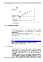
P share, I share, D share are added up and serve as adjustments to the firing rate default
of the fuel/air ratio control.
•
As long as the actual value is below setpoint, P term and I term are positive, that is to say
both of these terms will increase the firing rate default.
•
In such a case only D term has a negative value (assuming that boiler temperature is ris-
ing). Use D term carefully because it leads to a higher burden for the actuating elements.
•
In order to avoid excessive overshoot during burner start-up adjust parameters to achieve
a suitably large D term.
•
If despite a large setpoint deviation the burner is not run at full or base firing rate you
should increase the P term.
•
The longer you select the adjustment time the calmer the fuel/air ratio control. However,
this also increases the actual values’ deviation from setpoint value and leads to slower ad-
justment.
Adjustment of the values according to the controlled system is highly recommended.
8.1.11
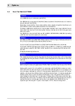
Aides for Setting
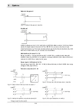
Fig. 8-6 Controller operation with P-term too high
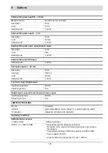
Hot Water Installations
Steam Boiler Installations
P term
120
280
600
I term
60
360
300
D term
20
50
25
Adjustment time
15
2
20
Characteristic
Control Process
Control Mode
Start-up Procedure
P term higher
decrease of
attenuation
stronger reaction with
overshoot
faster start-up with
overshoot
P term smaller
increase of
attenuation
less reaction, less ten-
dency to oscillate
slower startup
Characteristic
Control Process
Control Mode
Start-up Procedure
I term higher
decrease of atten-
uation
stronger reaction with
tendency to oscillate
faster start-up with ten-
dency to oscillate
I term smaller
increase of attenu-
ation
less reaction, less ten-
dency to oscillate
slower start-up
Summary of Contents for BT300 BurnerTronic
Page 2: ......
Page 25: ...24 3 Product Description Fig 3 9 Temperature derating BT300 for operation 2000 m NHN...
Page 49: ...48 4 Design and Functions Fig 4 20 Oil with pilot burner BT300...
Page 50: ...49 4 Design and Functions Fig 4 21 Oil without pilot burner BT300...
Page 51: ...50 4 Design and Functions Fig 4 22 Gas with pilot burner and leakage test BT300...
Page 52: ...51 4 Design and Functions Fig 4 23 Gas without pilot burner and leakage test BT300...
Page 53: ...52 4 Design and Functions Fig 4 24 Oil without pilot burner BT335...
Page 54: ...53 4 Design and Functions Fig 4 25 Gas without pilot burner and leakage test BT335...
Page 59: ...58 4 Design and Functions Fig 4 28 Leakage test process diagram...
Page 98: ...97 6 Operating Control and Displays...
Page 99: ...98 6 Operating Control and Displays...
Page 103: ...102 6 Operating Control and Displays...
Page 105: ...104 6 Operating Control and Displays...
Page 106: ...105 6 Operating Control and Displays...
Page 107: ...106 6 Operating Control and Displays...
Page 109: ...108 6 Operating Control and Displays...
Page 126: ...125 6 Operating Control and Displays 6 3 4 2 Curve Table Fig 6 37 Curve table window...
Page 246: ...242 10 EU Declaration of Conformity 10 EU Declaration of Conformity...
Page 247: ...243 10 EU Declaration of Conformity...


