


166
8
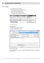
Options
8.1.3
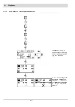
Operating Description
The burner start-up is carried out as described above. At least ’Burner ON’ signal and ’Re-
lease’ must be sent by firing rate controller.
The burner starts as soon as it is receiving signals ’Burner ON’ and ’Release’ from firing rate
controller. The firing rate controller is in operation not before the burner is running and the sig-
nal ’Control Release’ is pending.
The default value of firing rate for fuel/air ratio control is set via integral firing rate controller.
Depending on the difference between actual and setpoint value and adjusted control param-
eters this default firing rate value is set. When actual value is exceeding to maximum value
the firing rate controller switches OFF combustion.
The firing rate controller is active in AUTOMATIC mode only.
8.1.4
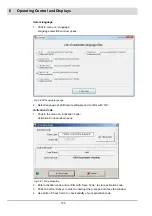
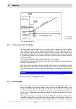
Control by atmospheric conditions and external setpoint presetting
Control by Atmospheric Conditions
If burner firing rate controller is configured as ’controlled by atmospheric conditions’ the set-
point value can be shifted between the parameter set setpoint minimum and setpoint maxi-
mum by connecting another Pt100/Pt1000 temperature sensor to the terminals 25, 26 and 27.
The controller by atmospheric conditions outside temperature is part of setpoint calculation.
As a result the operator is able to set minimum and maximum setpoint values determining final
setpoint value by outside temperature.
The setpoint min. is set at the lower limit of the outdoor temperature.
The setpoint max. is set at the upper limit of the outdoor temperature.
If the outdoor temperature limits are exceeded or not reached, the setpoints remain constant.
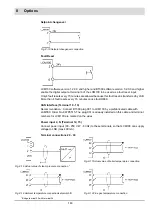
With activated option ’Control by atmospheric condition’ you may also implement external set-
point pre-setting.
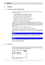
Fig. 8-2 Control by atmospheric conditions
Setpoint:
Value min
P 48/50
Value max
P 49/51
Lower limit
P 52
Upper limit
P 53
Summary of Contents for BT300 BurnerTronic
Page 2: ......
Page 25: ...24 3 Product Description Fig 3 9 Temperature derating BT300 for operation 2000 m NHN...
Page 49: ...48 4 Design and Functions Fig 4 20 Oil with pilot burner BT300...
Page 50: ...49 4 Design and Functions Fig 4 21 Oil without pilot burner BT300...
Page 51: ...50 4 Design and Functions Fig 4 22 Gas with pilot burner and leakage test BT300...
Page 52: ...51 4 Design and Functions Fig 4 23 Gas without pilot burner and leakage test BT300...
Page 53: ...52 4 Design and Functions Fig 4 24 Oil without pilot burner BT335...
Page 54: ...53 4 Design and Functions Fig 4 25 Gas without pilot burner and leakage test BT335...
Page 59: ...58 4 Design and Functions Fig 4 28 Leakage test process diagram...
Page 98: ...97 6 Operating Control and Displays...
Page 99: ...98 6 Operating Control and Displays...
Page 103: ...102 6 Operating Control and Displays...
Page 105: ...104 6 Operating Control and Displays...
Page 106: ...105 6 Operating Control and Displays...
Page 107: ...106 6 Operating Control and Displays...
Page 109: ...108 6 Operating Control and Displays...
Page 126: ...125 6 Operating Control and Displays 6 3 4 2 Curve Table Fig 6 37 Curve table window...
Page 246: ...242 10 EU Declaration of Conformity 10 EU Declaration of Conformity...
Page 247: ...243 10 EU Declaration of Conformity...


