


177
8
Options
Flu
e
gas te
m
pe
ra
tu
re
O
ut
side
t
em
p
er
at
ur
e/
setpoi
nt shift
Boile
r water
tem
per
atur
e/
Deactivation of po
w
er
contr
o
l uni
t
Steam
p
re
ssur
e
actual valu
e
Ma
nua
l r
e
gu
lar
fir
ing
r
ate inp
u
t
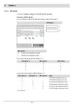
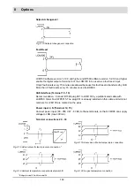
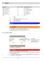
TPS (Three-Point-Step)
Potentiometer
0 ... 10 V
4 ... 20 mA
R
= 2.2 k
- 22 k
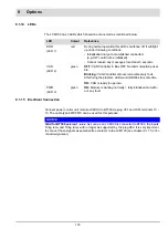
LED1
= Error
LED2
= CAN data traffic
LED3
= Power ON
GND
24
V
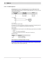
Oil fu
el meter
Gas
fuel meter
Setpoin
t cha
nge
over
Fa
ult
r
es
et
(L
C
M
v
1.
2.0
.0
a
nd
h
ighe
r)
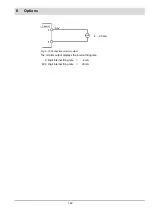
4 ... 20 mA
mo
n
itor
o
utpu
t (
+
)
4....
20
mA
m
onitor output
(-)
CAN Rx
CA
N
Tx
V5
VSS
N
L
C
A
N interfac
e
fr
om BT3
00
P
ower supply
Summary of Contents for BT300 BurnerTronic
Page 2: ......
Page 25: ...24 3 Product Description Fig 3 9 Temperature derating BT300 for operation 2000 m NHN...
Page 49: ...48 4 Design and Functions Fig 4 20 Oil with pilot burner BT300...
Page 50: ...49 4 Design and Functions Fig 4 21 Oil without pilot burner BT300...
Page 51: ...50 4 Design and Functions Fig 4 22 Gas with pilot burner and leakage test BT300...
Page 52: ...51 4 Design and Functions Fig 4 23 Gas without pilot burner and leakage test BT300...
Page 53: ...52 4 Design and Functions Fig 4 24 Oil without pilot burner BT335...
Page 54: ...53 4 Design and Functions Fig 4 25 Gas without pilot burner and leakage test BT335...
Page 59: ...58 4 Design and Functions Fig 4 28 Leakage test process diagram...
Page 98: ...97 6 Operating Control and Displays...
Page 99: ...98 6 Operating Control and Displays...
Page 103: ...102 6 Operating Control and Displays...
Page 105: ...104 6 Operating Control and Displays...
Page 106: ...105 6 Operating Control and Displays...
Page 107: ...106 6 Operating Control and Displays...
Page 109: ...108 6 Operating Control and Displays...
Page 126: ...125 6 Operating Control and Displays 6 3 4 2 Curve Table Fig 6 37 Curve table window...
Page 246: ...242 10 EU Declaration of Conformity 10 EU Declaration of Conformity...
Page 247: ...243 10 EU Declaration of Conformity...


