


174
8
Options
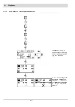
8.1.12 External/Manual Firing-rate Presetting (Terminals 16 - 19)
In order that LCM100 interprets the inputs as external firing rate presetting, LCM must be
activated by P 0040. Therefore set P0040 to value 1 or 2 or 3
2
.
With this setting UI300 still displays setpoint value and actual value of LCM100.With software
version 3.4.0.0(UI300) and 1.2.0.0 (LCM100) or higher P 0040 may be set to value 3. Setpoint
value and actual value are not displayed in UI300.
Short-circuit terminal 22 with terminal 23 and terminal 24.
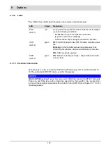
Select the type of external regular firing rateinput via P 0065.
NOTICE
With software version 1.1.0.0 or higher the LCM switches automatically to TPS input if
P 0065 = 2 (4 ... 20 mA) and input current <2,1 mA.
An input current of more than 3 mA ends this switch over.
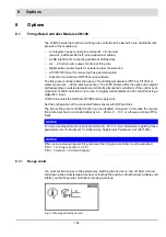
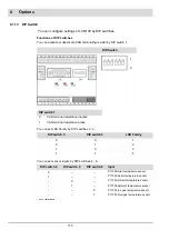
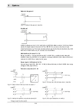
Connection external/manual regular firing rate input (Terminal 16 - 19)
Fig. 8-9 Connection possibilities of external firing rate input
NOTICE
If 0 ... 10 V input is used for the presetting of the firing rate the sensor must be able to load the
input of the LCM100 with 100
A to 0.
This is valid up to SN 16170050 only.
2
If the control is only performed on the external load, it can be set to the value 3 as of
version 1.4.0.0 of the LCM P0040. This means that neither the setpoint nor the actual
value are displayed in the UI300.
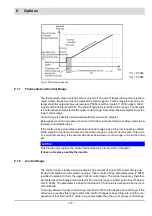
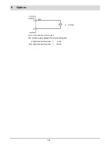
Scaling:
0 V/4 mA = 0 digit internal firing rate
10 V/20 mA = 999 digit internal firing rate
Summary of Contents for BT300 BurnerTronic
Page 2: ......
Page 25: ...24 3 Product Description Fig 3 9 Temperature derating BT300 for operation 2000 m NHN...
Page 49: ...48 4 Design and Functions Fig 4 20 Oil with pilot burner BT300...
Page 50: ...49 4 Design and Functions Fig 4 21 Oil without pilot burner BT300...
Page 51: ...50 4 Design and Functions Fig 4 22 Gas with pilot burner and leakage test BT300...
Page 52: ...51 4 Design and Functions Fig 4 23 Gas without pilot burner and leakage test BT300...
Page 53: ...52 4 Design and Functions Fig 4 24 Oil without pilot burner BT335...
Page 54: ...53 4 Design and Functions Fig 4 25 Gas without pilot burner and leakage test BT335...
Page 59: ...58 4 Design and Functions Fig 4 28 Leakage test process diagram...
Page 98: ...97 6 Operating Control and Displays...
Page 99: ...98 6 Operating Control and Displays...
Page 103: ...102 6 Operating Control and Displays...
Page 105: ...104 6 Operating Control and Displays...
Page 106: ...105 6 Operating Control and Displays...
Page 107: ...106 6 Operating Control and Displays...
Page 109: ...108 6 Operating Control and Displays...
Page 126: ...125 6 Operating Control and Displays 6 3 4 2 Curve Table Fig 6 37 Curve table window...
Page 246: ...242 10 EU Declaration of Conformity 10 EU Declaration of Conformity...
Page 247: ...243 10 EU Declaration of Conformity...


