


163
7
Maintenance
7.4
Replacing of BurnerTronic
DANGER!
Hazards due to electrical shock!
Dangerous tensions may be applied to the terminals of the BurnerControl. If the system is not
switched off, there is a risk of electric shock.
Before working in connection area disconnect all poles of the plant from power supply.
Prevent it from being switched back on and verify that the plant is voltage-free.
The cover of the BT300’s mounting cabinet may be opened by trained, qualified personnel
only.
WARNING!
Warning of dangerous conditions when replacing a burner control unit!
For replacement of burner control units take special precautions. Failure to observe the safety
instructions may result in dangerous conditions and malfunctioning.
Observe the safety instructions strictly!
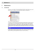
Transferring data to new burner control
1. Keep protected dataset of the plant ready where you wish to replace BT300.
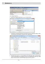
2. Make sure that the BT300 is the same type/mode or a superior grade one and has the
same customer ID as the BT300 to be replaced (origin of protected dataset).
NOTICE
To ensure a faultless functioning make sure that the same types/models or a superior grade
one are used.
3. Always select the protected dataset corresponding to the plant.
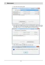
4. To activate new settings after the protected dataset is accepted, interrupt the power supply
and restart BT300.
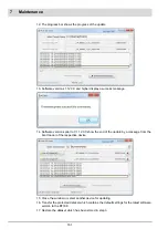
The imported dataset will set all device parameters. The safety-relevant parameters must
be checked on-site before the device is commissioned.
NOTICE
Check the safety-relevant parameters on-site before commissioning the device.
Summary of Contents for BT300 BurnerTronic
Page 2: ......
Page 25: ...24 3 Product Description Fig 3 9 Temperature derating BT300 for operation 2000 m NHN...
Page 49: ...48 4 Design and Functions Fig 4 20 Oil with pilot burner BT300...
Page 50: ...49 4 Design and Functions Fig 4 21 Oil without pilot burner BT300...
Page 51: ...50 4 Design and Functions Fig 4 22 Gas with pilot burner and leakage test BT300...
Page 52: ...51 4 Design and Functions Fig 4 23 Gas without pilot burner and leakage test BT300...
Page 53: ...52 4 Design and Functions Fig 4 24 Oil without pilot burner BT335...
Page 54: ...53 4 Design and Functions Fig 4 25 Gas without pilot burner and leakage test BT335...
Page 59: ...58 4 Design and Functions Fig 4 28 Leakage test process diagram...
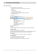
Page 98: ...97 6 Operating Control and Displays...
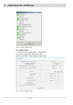
Page 99: ...98 6 Operating Control and Displays...
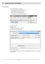
Page 103: ...102 6 Operating Control and Displays...
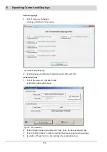
Page 105: ...104 6 Operating Control and Displays...
Page 106: ...105 6 Operating Control and Displays...
Page 107: ...106 6 Operating Control and Displays...
Page 109: ...108 6 Operating Control and Displays...
Page 126: ...125 6 Operating Control and Displays 6 3 4 2 Curve Table Fig 6 37 Curve table window...
Page 246: ...242 10 EU Declaration of Conformity 10 EU Declaration of Conformity...
Page 247: ...243 10 EU Declaration of Conformity...


