


243
8
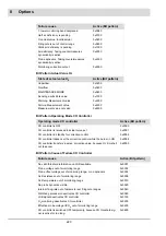
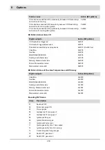
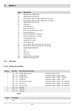
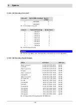
Options
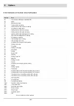
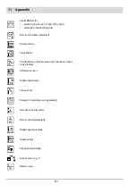
8.5.4.18 Allocation of the Texts to the Text Numbers
Tab. 8-29 Definition of text numbers
Text no.
Text
04
The correction influence is switched OFF
06
Starts
07
Maintenance mode
08
Fuel selection is missing.
09
Safety interlock chain system is missing.
10
Air pressure is still present.
11
Safety interlock chain oil is missing.
12
Safety interlock chain gas is missing.
13
Ignition position acknowledgement is missing.
14
High fire acknowledgement is missing.
15
Air pressure is missing.
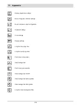
19
Valve leakage test is running.
20
Valve leakage test is OK.
21
Actuators are running to OPEN position.
22
Setting - pre-purge
23
Pre-purge
24
Setting - post-purge
25
Post-purge
26
Setting
28
Burner OFF
29
Standby
30
Setting - base fire
31
Base fire
32
Setting - Control
33
Control
35
Actuators are running to ignition position.
36
Ignition
37
Setting - ignition
38
Thermostat
39
Actuators didn’t reach the ignition position (HP), channel-
40
Actuators didn’t reach the ignition position (ÜP), channel-
41
The Actuator is not in aeration position (HP), channel-
42
The Actuator is not in aeration position (ÜP), channel-
43
Post-purge time:
44
Pre-purge time:
955
Permanent ventilation
1086
Fault 362 - burner maintenance
2001
Long ignition time
2002
Dynamics test is active.
2003
Burner release
2004
Miscell repair
2005
Automatic restart
2006
CPI
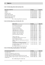
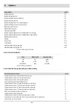
Summary of Contents for BT300 BurnerTronic
Page 2: ......
Page 25: ...24 3 Product Description Fig 3 9 Temperature derating BT300 for operation 2000 m NHN...
Page 49: ...48 4 Design and Functions Fig 4 20 Oil with pilot burner BT300...
Page 50: ...49 4 Design and Functions Fig 4 21 Oil without pilot burner BT300...
Page 51: ...50 4 Design and Functions Fig 4 22 Gas with pilot burner and leakage test BT300...
Page 52: ...51 4 Design and Functions Fig 4 23 Gas without pilot burner and leakage test BT300...
Page 53: ...52 4 Design and Functions Fig 4 24 Oil without pilot burner BT335...
Page 54: ...53 4 Design and Functions Fig 4 25 Gas without pilot burner and leakage test BT335...
Page 59: ...58 4 Design and Functions Fig 4 28 Leakage test process diagram...
Page 98: ...97 6 Operating Control and Displays...
Page 99: ...98 6 Operating Control and Displays...
Page 103: ...102 6 Operating Control and Displays...
Page 105: ...104 6 Operating Control and Displays...
Page 106: ...105 6 Operating Control and Displays...
Page 107: ...106 6 Operating Control and Displays...
Page 109: ...108 6 Operating Control and Displays...
Page 126: ...125 6 Operating Control and Displays 6 3 4 2 Curve Table Fig 6 37 Curve table window...
Page 246: ...242 10 EU Declaration of Conformity 10 EU Declaration of Conformity...
Page 247: ...243 10 EU Declaration of Conformity...


