


171
8
Options
value. In all other cases there is no shut-off range and burner is immediately shut-off when
reaching limit.
The burner 'ON' switching point can also be located above setpoint. In this case P0054 has to
be set negative (< 0).
8.1.9
Checking the Safety Limiter
For testing purposes of the safety limiter change the setpoint. This also causes a change in
shut-off range as well. The safety limiter can therefore be overrun in manual mode.
8.1.10 Control Mode
The firing rate controller is attempting to adjust actual value to setpoint value. A direct corre-
lation is assumed between internal firing rate and boiler temperature, i.e. the higher the inter-
nal firing rate, the faster boiler the rise of temperature. If curves are programmed in a different
way the firing rate controller will not operate.
Four parameters define the control characteristics:
•
Adjustment time
Adjustment time defines the intervals of deviation is checked and a new adjustment is de-
termined.
•
P term
The proportional term affects directly on deviation defined as difference between setpoint
value and actual value.
P > → higher step response
•
I term
The integral term is calculated from present deviation and previous deviation to setpoint
value.
I > → faster approximation to setpoint → danger of overshooting!
•
D term
The difference term is calculated from variation of actual values. This may result in accel-
erating, respectively retarding effects.
In practice adjustments of PID-controller is orientated by given controlled system. Out of char-
acteristics of the controlled system data can be deduced, i.e. by experimental determination.
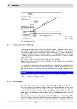
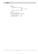
Fig. 8-5 Control range
*(1) = P 0056
*(2) = P 0055
*(3) = P 0054
*(4) = P 0048 - 0051
Summary of Contents for BT300 BurnerTronic
Page 2: ......
Page 25: ...24 3 Product Description Fig 3 9 Temperature derating BT300 for operation 2000 m NHN...
Page 49: ...48 4 Design and Functions Fig 4 20 Oil with pilot burner BT300...
Page 50: ...49 4 Design and Functions Fig 4 21 Oil without pilot burner BT300...
Page 51: ...50 4 Design and Functions Fig 4 22 Gas with pilot burner and leakage test BT300...
Page 52: ...51 4 Design and Functions Fig 4 23 Gas without pilot burner and leakage test BT300...
Page 53: ...52 4 Design and Functions Fig 4 24 Oil without pilot burner BT335...
Page 54: ...53 4 Design and Functions Fig 4 25 Gas without pilot burner and leakage test BT335...
Page 59: ...58 4 Design and Functions Fig 4 28 Leakage test process diagram...
Page 98: ...97 6 Operating Control and Displays...
Page 99: ...98 6 Operating Control and Displays...
Page 103: ...102 6 Operating Control and Displays...
Page 105: ...104 6 Operating Control and Displays...
Page 106: ...105 6 Operating Control and Displays...
Page 107: ...106 6 Operating Control and Displays...
Page 109: ...108 6 Operating Control and Displays...
Page 126: ...125 6 Operating Control and Displays 6 3 4 2 Curve Table Fig 6 37 Curve table window...
Page 246: ...242 10 EU Declaration of Conformity 10 EU Declaration of Conformity...
Page 247: ...243 10 EU Declaration of Conformity...


