


129
6
Operating Control and Displays
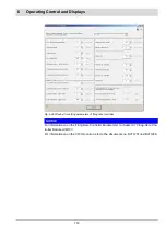
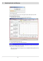
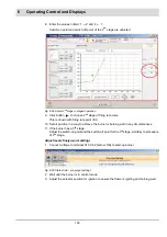
Take note of following information in this window:
–
A blue frame around curve and channels’ positioning information is indicating selection of
channels you want to set.
–
Fields ’Setpoint’ show respective setpoint position of the actuator.
–
Fields ’Actual Value’ show actual position of the actuator.
–
’Big’ diagram showing curve progression of selected channel.
–
Yellow point with red border showing position of selected curve point.
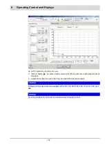
1. Change actuator position (actuating angle) of selected curve point with
buttons
and
.
2. Select curve points with buttons
and
to switch to another curve point.
NOTICE
These functions are not limited to window buttons of Fuel Air/ratio curves. The use of arrow
keys on the PC keyboard is possible as well.
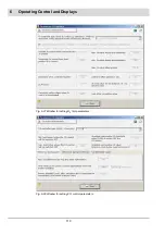
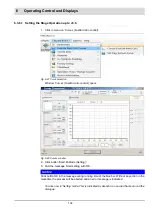
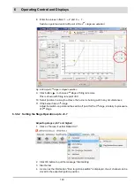
How to program a curve point
1. Select the internal firing rate of curve point 2 with button
. (Display button next to EI-
Mode).
2. Select channel 1, by clicking with cursor on ’small diagram’ below channel 1.
The data field of channel 1 is bordered blue.
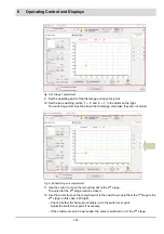
3. Set the actuator’s position for ignition position with buttons
and
.
4. Select channel 2, by clicking with the cursor on the ’small diagram’ below channel 2.
The data field of channel 2 is bordered blue.
5. Set the actuator’s position for ignition position with buttons
and
.
6. Proceed with channels 3 and 4 similarly, if existent and used.
7. Click on ’save point’ button.
The point is stored.
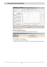
The feedback of channel 4’s setpoint curve must increase continuously.
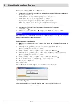
As soon as you store the point new program data is read in again from BT300.
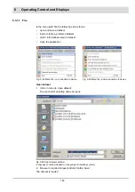
Fig. 6-41 Reading values
Summary of Contents for BT300 BurnerTronic
Page 2: ......
Page 25: ...24 3 Product Description Fig 3 9 Temperature derating BT300 for operation 2000 m NHN...
Page 49: ...48 4 Design and Functions Fig 4 20 Oil with pilot burner BT300...
Page 50: ...49 4 Design and Functions Fig 4 21 Oil without pilot burner BT300...
Page 51: ...50 4 Design and Functions Fig 4 22 Gas with pilot burner and leakage test BT300...
Page 52: ...51 4 Design and Functions Fig 4 23 Gas without pilot burner and leakage test BT300...
Page 53: ...52 4 Design and Functions Fig 4 24 Oil without pilot burner BT335...
Page 54: ...53 4 Design and Functions Fig 4 25 Gas without pilot burner and leakage test BT335...
Page 59: ...58 4 Design and Functions Fig 4 28 Leakage test process diagram...
Page 98: ...97 6 Operating Control and Displays...
Page 99: ...98 6 Operating Control and Displays...
Page 103: ...102 6 Operating Control and Displays...
Page 105: ...104 6 Operating Control and Displays...
Page 106: ...105 6 Operating Control and Displays...
Page 107: ...106 6 Operating Control and Displays...
Page 109: ...108 6 Operating Control and Displays...
Page 126: ...125 6 Operating Control and Displays 6 3 4 2 Curve Table Fig 6 37 Curve table window...
Page 246: ...242 10 EU Declaration of Conformity 10 EU Declaration of Conformity...
Page 247: ...243 10 EU Declaration of Conformity...


