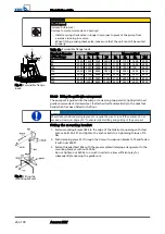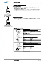
Fitting the guide rails
CAUTION
Improper installation of the guide rails
Damage to the guide rail arrangement!
▷
Always adjust the guide rails so that they are in a perfectly vertical position.
1. Place rails 710 onto the conical bosses provided on duckfoot bend 72-1 and
position vertically.
2. Mark the length of rails 710 (up to the lower edge of the mounting brackets),
taking into account the adjusting range of the slotted holes in mounting bracket
894.
3. Shorten rails 710 with a 90° cut to the pipe axis. Debur the rails inside and
outside.
4. Insert mounting bracket 894 with elastic sleeves 520.37 into guide rails 710 until
the mounting bracket rests on the rail ends.
5. Tighten nuts 920.37.
This pulls clamping sleeves 81-51.37 upwards and expands sleeves 520.37 against
the inside pipe diameter.
6. Secure nut 920.37 with a second nut.
NOTE
For installation depths > 6 m, the scope of supply may include brackets as a middle
support for the guide rails. The mounting brackets also serve as spacers between the
two guide rails.
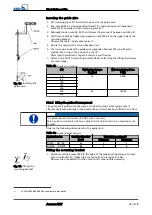
Fitting the middle support
1. Measure the inside diameter of the guide rails.
2. Expand elastic sleeves 520.39 with clamping sleeves 81-51.39 to the inside
diameter of the guide rails by tightening nuts 920.39.
3. Slip the guide rails onto the sleeves and check whether there is a tight fit
between the guide rails and the sleeves.
4. Secure the fasteners with locknuts.
5. Proceed to fit the guide rails.
5.3.1.5 Preparing the pump set
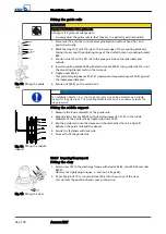
Fitting the claw
1. Fasten claw 732 to the discharge flange with studs 902.35, discs 550.35 and nuts
920.35.
Observe the tightening torques. (
2. Fit profile joint 410 or round cord seal 99-6 into the groove of the claw.
This will seal the duckfoot bend / pump connection.
920.37
894
520.37
81-51.37
901.37
710
Fig. 12: Fitting the guide
rails
Fig. 13: Fitting the middle
support
902.35
732
550.35
920.35
Fig. 14: Fitting the claw
5 Installation at Site
26 of 78
Amarex KRT
Summary of Contents for Amarex KRT
Page 77: ......


