▪
Make sure the surface of the shaft is absolutely clean and undamaged.
▪
Before the actual installation of the mechanical seal, wet the contact faces with a
drop of oil.
▪
For easier installation of bellows-type mechanical seals, wet the inside diameter
of the bellows with soapy water (no oil).
▪
To prevent any damage to the rubber bellows, place a thin foil (thickness
approximately 0.1 to 0.3 mm) around the free shaft stub.
Slip the rotating assembly over the foil into its installation position.
Then remove the foil.
✓
The shaft and rolling element bearings have been properly installed in the
motor.
1. Push drive-end mechanical seal 433.01 onto shaft 210 and secure it with taper
lock ring 515 or circlip 932.03.
2. Insert O-rings 412.04/412.35 and 412.15/412.11 into discharge cover 163, and
press them into bearing bracket 330 as far as they will go.
3. Push pump-end mechanical seal 433.02 onto shaft 210.
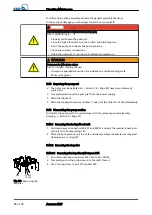
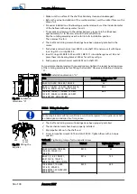
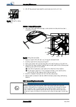
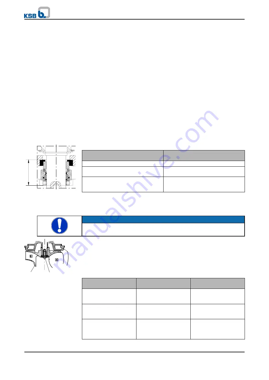
For special mechanical seals with covered springs, tighten the socket head cap screw
at the rotating assembly before fitting the impeller. Observe installation dimension
"A".
Table 23: Installation dimension "A"
Size
Installation dimension "A"
[mm]
40-250, 80-250, 100-240, 100-250
29
80-251, 100-251, 150-251, 80-315/-316,
150-315, 200-315/-316, 100-315/316
38.5
100-400, 100-401, 150-400, 150-401,
151-401, 200-330, 200-400, 200-401,
250-400/-401, 300-400/-401
48.3
7.5.2.2 Fitting the impeller
NOTE
For bearing brackets with tapered fit make sure that the tapered fit of impeller and shaft
is undamaged and installed free from grease.
✓
The shaft and rolling element bearings have been properly installed.
✓
The mechanical seals have been properly installed.
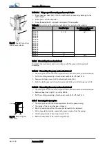
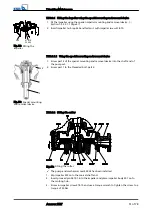
1. Slip impeller 230 onto the shaft end.
2. Screw in impeller screw 914.10 and disc 550.23. Tighten them with a torque
wrench.
Table 24: Tightening torque for the impeller screw
Size
Thread
Tightening torque
[Nm]
40-250, 80-250, 100-240,
100-250, 150-251, D
100-251
M 10
35
80-251, F, E, K 100-251,
80-315/-316, 150-315,
200-315/-316, 100-315/316
M 16
150
100-400/401, 150-400,
151-401, 200-330,
200-400/401, 250-400/-401,
300-400/-401
M 20
290
A
Fig. 26: Installation
dimension "A"
914.10
550.23
230
Fig. 27: Fitting the
impeller
7 Servicing/Maintenance
50 of 78
Amarex KRT
Summary of Contents for Amarex KRT
Page 77: ......


