background image

 INSTALLATION 

2

13

OPTISONIC 6300

www.krohne.com

06/2019 - 4005857501 - QS OPTISONIC 6300 v2 R01 en 

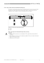
2.8.1  Inlet, outlet and recommended mounting area

To perform an accurate flow measurement preferably mount the sensor rail at least 10 DN 
downstream of a flow disturbance like elbow, valve, header or pump. Please follow the 
installation recommendations in the next installation position examples.

Note: especially for XT (eXtended Temperature) versions:

Figure 2-9: Inlet, outlet and recommended mounting area

1  

t

 10 DN

2  

t

  5 DN

3  

OK, 120

°

CAUTION!

 Always install the sensor at a non-insulated part of the pipe. Remove any insulation if 
necessary!

After installation, the sensor can be completely insulated. The sensor cable must be kept 
away from the hot pipe surface.

Always wear protective gloves.

Summary of Contents for OPTISONIC 6300

Page 1: ...Ultrasonic clamp on flowmeter ER 4 0 0_ OPTISONIC 6300 OPTISONIC 6300 OPTISONIC 6300 OPTISONIC 6300 Quick Start Quick Start Quick Start Quick Start KROHNE 06 2019 4005857501 QS OPTISONIC 6300 v2 R01 en ...

Page 2: ...ers and sensor construction 17 2 8 10 Pipe and media parameters 17 2 9 Installation of the flowmeter 18 2 9 1 General mechanical installation 18 2 9 2 Installation of solid contact material 20 2 9 3 Installation instructions for small and medium version 22 2 9 4 Mechanical installation of large version 24 2 9 5 Mounting the UP rail 24 2 9 6 Mounting the DOWN rail 25 2 9 7 Configuration instruction...

Page 3: ... 43 4 Start up 44 4 1 General instructions for programming 44 4 2 Start measurement standard setup 45 4 3 Start measurement of large version 46 4 4 Mechanical installation for large version 48 5 Technical data 53 5 1 Dimensions and weight 53 5 1 1 Clamp on sensor and splitter cable box 53 5 1 2 Mounting plate of field housing 55 5 1 3 Mounting plate of wall mounted housing 55 ...

Page 4: ...these instructions can result in damage to the device or to parts of the operator s plant INFORMATION These instructions contain important information for the handling of the device CAUTION Installation assembly start up and maintenance may only be performed by appropriately trained personnel The regional occupational health and safety directives must always be observed LEGAL NOTICE The responsibi...

Page 5: ... grease mineral standard versions or high temperature contact XT versions Coupling pads CAUTION Responsibility for the use of the measuring devices with regard to suitability intended use and corrosion resistance of the used materials against the measured fluid lies solely with the operator INFORMATION The manufacturer is not liable for any damage resulting from improper use or use for other than ...

Page 6: ...emperature contact gel XT versions 8 Coupling pads 9 Signal cable plus connector cap XT versions have a protection sleeve around the signal cable INFORMATION Assembly materials and tools are not part of the delivery Use the assembly materials and tools in compliance with the applicable occupational health and safety directives Figure 2 2 Additionally for large version 1 2nd sensor plus cover 2 90 ...

Page 7: ...fic information and extensive product specification is available using PICK the Product Information Center KROHNE web tool PICK can be found via the service menu button on the KROHNE com website Figure 2 3 System configuration possibilities 1 One sensor with a converter in wall mount 1 or field version 5 2 Two sensors with a converter in wall mount 2 or field version 6 X mode 3 Two sensors with a ...

Page 8: ... converters field or wall version Figure 2 5 Example of nameplate UFC 300 F field version 1 Ambient temperature 2 Protection class and Tag number 3 Mains supply data 4 Electronic Revision number 5 Sensor serial number s corresponds with the number mentioned on type sticker 6 Manufacturing date and CE sign with number s of notified body bodies 7 Type designation of the flowmeter with CG number 8 Na...

Page 9: ...acturer 2 Device type 3 Manufacturing year 4 Serial number sensor 1 short code flow sensor 5 Electronic Revision number 6 Mains supply data Figure 2 7 Nameplate of the flow sensor example 1 Ambient temperature operating range 2 Protection category 3 Tag number 4 CE sign with number s of notified body bodies 5 Media temperature and calibration data 6 Type designation of the flowmeter 7 Name and add...

Page 10: ...ive mode external power supply required for operation of the subsequent devices N C connection terminals not connected 2 5 Storage Store the flowmeter in a dry and dust free location Avoid lasting direct exposure to the sun Store the flowmeter in its original packing Storage temperature 50 70 C 58 158 F 2 6 Transport Signal converter Do not lift the signal converter by the cable glands Measuring s...

Page 11: ...ate space on the sides Protect the signal converter from direct sunlight and install a sunshade if necessary Signal converters installed in control cabinets require adequate cooling e g by fan or heat exchanger Do not expose the signal converter to intense vibrations and mechanical shocks INFORMATION To avoid measuring errors and malfunctioning of the flowmeter due to gas or air inclusions or an e...

Page 12: ...re fitting the transducer to the transducer knob in the sensor rail check the connection groove of the transducer cover for damages or dirt Clean or replace when dirty or damaged Check sensor cabling at regular intervals for damages and wear as this may cause improper functioning Replace when necessary Check the sensor rail sliding area regularly for dirt or other pollution or excess coupling fat ...

Page 13: ...r or pump Please follow the installation recommendations in the next installation position examples Note especially for XT eXtended Temperature versions Figure 2 9 Inlet outlet and recommended mounting area 1 t 10 DN 2 t 5 DN 3 OK 120 CAUTION Always install the sensor at a non insulated part of the pipe Remove any insulation if necessary After installation the sensor can be completely insulated Th...

Page 14: ...r no flow rates 2 8 3 Bends in 2 or 3 dimensions Figure 2 10 Long horizontal pipes INFORMATION 2 dimensional bends occur in a vertical or or or or horizontal plane X Y only while 3 dimensional bends occur in both vertical and and and and horizontal plane X Y Z Figure 3 3 2 and or 3 dimensional bends upstream of the flowmeter 1 2 dimensions X Y 2 3 dimensions X Y Z for 2 path using bends in 2 dimen...

Page 15: ... 6300 www krohne com 06 2019 4005857501 QS OPTISONIC 6300 v2 R01 en 2 8 4 T section 2 8 5 Bends Figure 2 12 Distance behind a T section 1 t 20 DN Figure 2 13 Installation in bending pipes Figure 2 14 Installation in bending pipes ...

Page 16: ...rough the meter 2 8 7 Position of pump 2 8 8 Position of control valve Always install control valves downstream of the flowmeter in order to avoid cavitation or distortion of the flow profile Figure 2 15 Open feed or discharge CAUTION Never install the flowmeter at a pump suction side in order to avoid cavitation or flashing in the flowmeter Figure 2 16 Position of pump Figure 2 17 Position of con...

Page 17: ...ter range Preferred measuring Preferred measuring Preferred measuring Preferred measuring modes modes modes modes Possible measuring Possible measuring Possible measuring Possible measuring modes modes modes modes Small DN15 100 0 5 4 DN25 W mode 4 traverses Small V mode t DN25 V mode 2 traverses Medium DN50 400 2 16 V mode 2 traverses DN200 1250 8 50 X mode 2 x 1 traverses Large DN200 4000 8 160 ...

Page 18: ...Installation of the rails with the metal straps Installation of the rails with the metal straps 1 guide one end of the metal strap through the lower strap lock on both the side of the sensor rail 2 3 4 wrap both metal strap around the piping 5 return the other end of the metal strap through the upper strap lock on both the side of the sensor rail 2 6 tighten and lock the strap locks with an Allen ...

Page 19: ...advised mounting distance 3 menu X7 2 3 Lock the transducer by turning the locking knob 1 clockwise Greasing the transducer surfaces Greasing the transducer surfaces Greasing the transducer surfaces Greasing the transducer surfaces 1 press in both locking strips on the left and right end of the sensor rail 2 lift the cover in vertical movement then tilt over the cover 90 3 4 put grease on the cont...

Page 20: ...r signal quality compared to contact grease The signal strength will be stable over time and therefore lower start up signal strength is acceptable In case of insufficient signal strength only contact grease can be used Installation and optimization should first be done using contact grease After finding the optimal position use the click and turn mechanism to install the pads Apply a thin layer o...

Page 21: ...the sensor rail 2 lift the sensor rail in vertical movement then tilt over the sensor rail 90 3 4 put grease on both sides of the pads 5 place the pads on the transducer surfaces 6 put back sensor rail by tilting back in a 90 angle 7 press the sensor rail back vertically on the fixing units until you hear them click Applying solid contact material pads ...

Page 22: ...QS OPTISONIC 6300 v2 R01 en 2 9 3 Installation instructions for small and medium version Figure 2 19 Procedure for installation of small or medium version 1 Rail small version 2 Rail medium version 3 Choose for V mode or 4 Choose for W mode 5 Make settings in converter ...

Page 23: ...dard installation options Figure 2 20 Device configurations Small and Medium 1 Single pipe single path version 2 Single pipe dual path version 3 Dual pipe single path version 4 Single pipe dual path in X Mode INFORMATION Refer to the manual of the OPTISONIC 6300 for more information regarding X mode ...

Page 24: ...rallel to the pipe Mount the fixing units and the cable box as shown below Figure 2 21 Mounting large version rail 1 Pull the metal strap through the upper slit of the UP rail 2 Take the metal strap around the pipe 45 60 3 Push the end of the metal strap into the lower slot of the fixing unit 4 Take the other side of the metal strap around the pipe to the fixing unit 5 Mount the cable box only for...

Page 25: ...ation are with the use of a fixed reference point or determination of transducer position with the use of a paper plastic material roll For more details refer to Mechanical installation for large version on page 48 2 9 7 Configuration instructions for large version á Finish the installation menu Figure 2 22 Procedure for installation of large version 1 Enter the values for the installation menu X1...

Page 26: ...h 4 Dual pipe INFORMATION Option 1 can not be used in case of a 2 path configuration For detailed information of the programming and settings refer to General instructions for programming on page 44 or Start measurement of large version on page 46 INFORMATION Information and details for the mechanical installation refer to the manual of the OPTISONIC 6300 and for the electrical connections refer t...

Page 27: ...nting 1 Fix the signal converter to the pipe 2 Fasten the signal converter using standard U bolts and washers 3 Tighten the nuts INFORMATION Assembly materials and tools are not part of the delivery Use the assembly materials and tools in compliance with the applicable occupational health and safety directives Figure 2 24 Pipe mounting of the field housing ...

Page 28: ...mation refer to Mounting plate of field housing on page 55 2 Use the mounting material and tools in compliance with the applicable occupational health and safety directives 3 Fasten the housing securely to the wall 4 Screw the signal converter to the mounting plate with the nuts and washers Figure 2 25 Wall mounting of the field housing Figure 2 26 Mounting multiple devices next to each other a t ...

Page 29: ... of the mounting plate For further information refer to Mounting plate of wall mounted housing on page 55 2 Fasten the mounting plate securely to the wall 3 Screw the signal converter to the mounting plate with the nuts and washers Figure 2 27 Wall mounting of the wall mounted housing Figure 2 28 Mounting multiple devices next to each other a t 240 mm 9 4 ...

Page 30: ...of the display 3 Pull out the display between the two metal puller devices and rotate it to the required position 4 Slide the display and then the metal puller devices back into the housing 5 Re fit the cover and tighten it by hand Figure 2 29 Turning the display of the field housing version CAUTION The ribbon cable of the display must not be folded or twisted repeatedly INFORMATION Each time a ho...

Page 31: ...h the power disconnected Take note of the voltage data on the nameplate DANGER Observe the national regulations for electrical installations DANGER For devices used in hazardous areas additional safety notes apply please refer to the Ex documentation WARNING Observe without fail the local occupational health and safety regulations Any work done on the electrical components of the measuring device ...

Page 32: ...er electronics compartment 2 Cover terminal compartment for power supply and inputs outputs 3 Connectors for power 4 Connectors for inputs outputs 5 Connectors for sensor cable 6 Cover sensor terminal compartment Wall version Figure 3 3 Construction of wall version 1 Signal cable for sensors 2 Communication I O 3 Power supply 24 VAC DC or 100 230 VAC WARNING This is a Class A product In a domestic...

Page 33: ...chable by the operator and marked as the disconnecting device for this equipment The switch or circuit breaker and wiring has to be suitable for the application and shall also be in accordance with the local safety requirements of the building installation e g IEC 60947 1 3 INFORMATION For devices used in hazardous areas additional safety notes apply please refer to the Ex documentation INFORMATIO...

Page 34: ...erminal in the terminal compartment of the signal converter When connecting to functional extra low voltages provide a facility for protective separation PELV acc to VDE 0100 VDE 0106 and or IEC 60364 IEC 61140 or relevant national regulations 3 4 1 Signal converter power supply connections INFORMATION For 24 VDC 12 VDC 10 is included in the tolerance range Field version Figure 3 5 Signal converte...

Page 35: ...ion 1 Connect the green cable to DOWN 2 Connect the blue cable to UP 3 Turn the screws clockwise to secure the cap Figure 3 8 Connect the signal cable in case of stainless steel XT version 1 Put in the connector 2 Turn knob to secure the connector A positioning notch in connector female on cable B positioning cam in connector male on sensor device CAUTION When attaching the connector make sure tha...

Page 36: ...P rail 2 Connect the green cable to the DOWN rail 3 Make connections in cable box 4 Cable to converter 5 Turn the screws clockwise to secure the caps CAUTION To ensure smooth functioning always use the signal cable s included in the delivery CAUTION When installing the EMC gland make sure that the shield of the cable has a good contact with the internal metalised insert of the EMC gland ...

Page 37: ...0 Connect signal cable Construction of console F version Figure 3 11 Inserting cable and secure with clamp on shielding bush 1 Cables 2 Cable glands 3 Grounding clamps 4 Cable with metal shielding bush CAUTION Re connecting of the coax connectors is limited Make sure that the male connector on the coax cable is always put straight on the female connector in the connection terminal of the unit Exce...

Page 38: ...2 Open connection terminal 3 Tool for releasing connectors 4 How to use the release tool 5 Marking on the cables 6 Insert cable s into connection terminal Construction of console W version Figure 3 13 Inserting cable and secure with clamp on shielding bush 1 Connection compartiment sensor cable s 2 Grounding clamp with metal shielding bush of sensor cable Wall version Figure 3 14 Connect signal ca...

Page 39: ...nly be carried out with the power disconnected Take note of the voltage data on the nameplate INFORMATION For frequencies above 100 Hz shielded cables are to be used in order to reduce effects from electrical interferences EMC CAUTION Observe connection polarity Field version Figure 3 15 Terminal compartment for inputs and outputs of the field housing INFORMATION Each time a housing cover is opene...

Page 40: ...ise Open bottom cover terminal compartment Push the prepared cable through the cable entry 2 and connect the necessary conductors 3 Connect the shield if necessary 4 Close the cover of the terminal compartment Lock 5 the housing cover with screw driver counter clockwise Wall version Figure 3 16 Terminal compartment for inputs and outputs of the wall mounted housing ...

Page 41: ...0 x1 100 100 230 VAC standard display basic I O Ia or Ip Sp Cp Sp Pp Sp CG 370 x1 7FK 100 230 VAC standard display modular I O Ia PN SN and optional module PN SN CN Abbreviation Identifier for CG No Description Ia A Active current output Ip B Passive current output Pa Sa C Active pulse output frequency output status output or limit switch changeable Pp Sp E Passive pulse output frequency output st...

Page 42: ...c I Os standard 1 0 0 Ip HART passive 1 Sp Cp passive 2 Sp passive Pp Sp passive 2 Ia HART active 1 Ex i I Os option 2 0 0 Ia HART active PN SN NAMUR 2 3 0 0 Ip HART passive PN SN NAMUR 2 2 1 0 Ia active PN SN NAMUR Cp passive 2 Ia HART active PN SN NAMUR 2 3 1 0 Ia active PN SN NAMUR Cp passive 2 Ip HART passive PN SN NAMUR 2 2 2 0 Ip passive PN SN NAMUR Cp passive 2 Ia HART active PN SN NAMUR 2 ...

Page 43: ...nals A A A B B C C D D Modular IOs option 4 _ _ max 2 optional modules for term A B Ia HART active Pa Sa active 1 8 _ _ max 2 optional modules for term A B Ip HART passive Pa Sa active 1 6 _ _ max 2 optional modules for term A B Ia HART active Pp Sp passive 1 B _ _ max 2 optional modules for term A B Ip HART passive Pp Sp passive 1 7 _ _ max 2 optional modules for term A B Ia HART active PN SN NAM...

Page 44: ...ion menu Start installation menu Start installation menu Connect converter to power supply and power up converter Keep left button pressed until in display appears release key now Figure 4 1 First and second page appear intermittently CAUTION If you program the diameter use the outer diameter of the pipe For improved accuracy fill in as much details as possible Fill in the actual transducer distan...

Page 45: ...l á Optimization loop Repeat steps X7 2 7 until the advised mounting distance does not change more than 0 5 á X7 2 7 Optimise distance yes no read actual velocity of sound of fluid new velocity of sound of fluid yes no confirm or adjust velocity of sound Read the advised mounting distance and position the transducer at that distance Press enter á X7 2 8 Read the actual volume flow á X7 2 9 Path re...

Page 46: ... 3 Read the advised mounting distance Write it down you need it later The installation menu can be closed continue with mechanical and electrical installation i Mounting distance Mounting distance Mounting distance Mounting distance The advised mounting distance is needed when continuing with the configuration Proceed with the mechanical installation of the rails refer to Mechanical installation o...

Page 47: ... CAUTION Choose between Z and V mode before you proceed The advised distance menu X7 2 3 must be 246 mm 9 7 for V mode Figure 4 3 Device configurations for Large versions 1 Single pipe single path with cable 5 m 2 Single pipe single path with cable 10 m 3 Single pipe dual path 4 Dual pipe 4 ...

Page 48: ...pe Mount the fixing units and the cable box as shown below Figure 4 4 Mounting large version rail 1 Pull the metal strap through the upper slit of the UP rail 2 Take the metal strap around the pipe 45 60 3 Push the end of the metal strap into the lower slot of the fixing unit 4 Take the other side of the metal strap around the pipe to the fixing unit 5 Mount the cable box only for the downstream m...

Page 49: ...rail at the opposite location at the pipe There are two possible ways to find the exact location Find the location with a fixed reference point Calculate the half of the circumference Mark this 180 alignment line on the pipe Mount the DOWN rail in such a way that the transducer is at the marked location Figure 4 5 Find the opposite location with a reference point 1 Measure the distance between the...

Page 50: ...close beside each other Figure 4 6 Marking the opposite location Calculate the middle of the alignment line between the 4 V marks as shown Figure 4 7 Finding the location for the DOWN rail 1 Advised Distance as shown in menu X7 4 2 Measure the distance between the transducer and the end of the UP rail 3 Determine and mark the location of the transducer of the DOWN rail 3 3 3 3 1 1 1 1 2 2 2 2 INFO...

Page 51: ...e DOWN rail in V mode For V mode you must install the DOWN rail in line with the UP rail It is easier to install than the Z mode but you need more free pipe length V mode is possible for DN450 600 2000 minimum depends on application Figure 4 9 Mounting large version in V mode 1 Fixing units 2 Reference marking 3 Cable box 4 Advised Distance X7 4 5 Minimum distance between UP and DOWN rail 110 mm 4...

Page 52: ...s Electrical connections Figure 4 10 Connections in splitter cable box large version 1 Connect the blue cable to the UP rail 2 Connect the green cable to the DOWN rail 3 Make connections in splitter cable box 4 Cable to converter 5 Turn the screws clockwise to secure the caps INFORMATION See also the previous sections Installation and Electrical connections ...

Page 53: ...tainless steel XT 2 493 65 5 48 2 0 Medium stainless steel XT 2 823 65 5 48 2 6 Table 5 1 Dimensions and weight clamp on sensor mm kg 1 value for one of the 2 delivered rails 2 delivered without cover Version Dimensions inches Approx weight without cable strip lbs L H W Small 19 5 2 8 2 5 5 5 Medium 32 5 2 8 2 5 7 6 Large 19 5 1 2 8 1 2 5 1 10 2 Small stainless steel XT 2 19 4 2 6 1 9 4 4 Medium s...

Page 54: ...ion splitter cable boxbox Dimensions mm Approximately weight without cable kg a b c Cable box 115 210 67 0 9 Table 5 3 Dimensions and weight splitter cable box mm kg Dimensions inches Approximately weight without cable lbs a b c Cable box 4 53 8 27 2 64 2 0 Table 5 4 Dimensions and weight splitter cable box inch lb ...

Page 55: ...nting plate of wall mounted housing Figure 5 3 Dimensions for mounting plate of field housing mm inch a 72 2 8 b 72 2 8 c Ø9 Ø0 4 Table 5 5 Dimensions in mm and inch Figure 5 4 Dimensions of mounting plate of wall mounted housing mm inch a Ø9 Ø0 4 b 64 2 5 c 16 0 6 d 6 0 2 e 63 2 5 f 13 0 5 g 64 2 5 h 98 3 85 Table 5 6 Dimensions in mm and inch ...

Page 56: ...vices Head Office KROHNE Messtechnik GmbH Ludwig Krohne Str 5 47058 Duisburg Germany Tel 49 203 301 0 Fax 49 203 301 10389 info krohne com KROHNE 06 2019 4005857501 QS OPTISONIC 6300 v2 R01 en Subject to change without notice The current list of all KROHNE contacts and addresses can be found at www krohne com ...

Reviews: