4.9 Service procedure
Maintenance
Every 2000 hours service
WA500-6H – VEAM430100
4-77
CAUTION
When removing the filter cover, keep the filter pressed down by
hand. The filter cover is being pushed by a spring, so if the filter
cover mounting bolts are removed carelessly, there is danger
that the filter cover will spring out and cause injury.
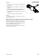
9. Hold filter cover (4) at the top of the hydraulic tank down by
hand, remove mounting bolts (5), then remove the cover
slowly.
10. Remove spring (6) and bypass valve (7), then take out ele-
ment (8).
11. Check that there is no foreign material inside the tank, then
clean it.
12. Install a new element, then place bypass valve (7), spring
(6), and cover (4) into the tank.
13. Replace cover O-ring (9) with a new one.
14. Hold filter cover (4) down by hand and tighten the mounting
bolts uniformly.
15. Add engine oil through oil filler port (F) to the specified level,
then install cap.
16. Check that the hydraulic oil is at the specified level.
For details, see "Check oil level in hydraulic tank, add oil
(4-53)".
17. Run the engine at low idling, and extend and retract the
steering, bucket, and lift arm cylinders 4 to 5 times. Be care-
ful not to operate the cylinder to the end of its stroke (stop
approx.100 mm (3.9 in) before the end of stroke).
NOTE
If the engine is run immediately at high speed or the cylinder is
operated to the end of its stroke, the air inside the cylinder will
cause damage to the piston packing.
18. Next, operate the steering, bucket, and lift arm cylinders to
the end of their stroke 3 to 4 times, then stop the engine and
loosen vent plug (1) to bleed the air from the hydraulic tank.
After bleeding the air, tighten plug (1) again.
19. Check the hydraulic oil level and add oil to the specified
level.
For details, see "Check oil level in hydraulic tank, add oil
(4-53)".
20. Run the engine at low idle, loosen the air bleeding plug (1) to
bleed the air from inside the filter tank.
21. Next, increase the engine speed and repeat the procedure in
Step 16 to bleed the air. Continue this operation until no
more air comes out from plug (1).
GK050256
5
4
9
6
7
8
GK050214
1
F
Summary of Contents for WA500-6H
Page 2: ......
Page 3: ...Foreword WA500 6H VEAM430100 1 1 1 Foreword...
Page 26: ...1 7 CE Conforming equipment Foreword 1 24 WA500 6H VEAM430100...
Page 254: ...3 7 Troubleshooting Operation 3 188 WA500 6H VEAM430100...
Page 344: ...4 9 Service procedure Every 12000 hours service Maintenance 4 90 WA500 6H VEAM430100...
Page 345: ...Technical Data WA500 6H VEAM430100 5 1 5 Technical Data...
Page 347: ...Technical Data 5 1 Technical data WA500 6H VEAM430100 5 3 GK032301 A B H I G C E F D...
Page 352: ...5 4 Limit values for slopes Technical Data 5 8 WA500 6H VEAM430100...
Page 401: ...Index WA500 6H VEAM430100 7 1 7 Index...
Page 407: ...Notes WA500 6H VEAM430100 8 1 8 Notes...
Page 408: ...Notes 8 2 WA500 6H VEAM430100...
Page 409: ...Notes WA500 6H VEAM430100 8 3...
Page 410: ...Notes 8 4 WA500 6H VEAM430100...
Page 411: ...Notes WA500 6H VEAM430100 8 5...
Page 412: ...Notes 8 6 WA500 6H VEAM430100...


