Operation
3.3 Operation
WA500-6H – VEAM430100
3-151
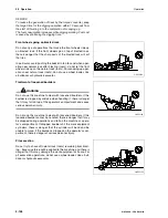
3. Remove mounting bolt (3).
4. Pull out and remove bucket hinge pin (4) on both sides of the
bucket.
5. Disconnect the lift arm and bucket.
(A) Lift arm
(B) Bucket link
(C) Bucket
Installing the bucket
Before installing the bucket, remove all grease and sand or mud
from around the pins, pin holes, and boss, then wash the parts.
After washing, coat the pins and the inside of the pin holes with
fresh grease.
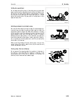
1. Set cord ring (2) on top of lift arm boss (1) as shown in the
diagram.
After completion of assembly of the bucket and adjustment
with shims in step 6, move the cord ring down to the groove.
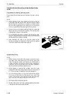
2. Coat dust seal lip portion (3) with grease.
GK050162
3
GK050163
4
GK050164
A
B
C
GK050165
1
2
2
3
3
Summary of Contents for WA500-6H
Page 2: ......
Page 3: ...Foreword WA500 6H VEAM430100 1 1 1 Foreword...
Page 26: ...1 7 CE Conforming equipment Foreword 1 24 WA500 6H VEAM430100...
Page 254: ...3 7 Troubleshooting Operation 3 188 WA500 6H VEAM430100...
Page 344: ...4 9 Service procedure Every 12000 hours service Maintenance 4 90 WA500 6H VEAM430100...
Page 345: ...Technical Data WA500 6H VEAM430100 5 1 5 Technical Data...
Page 347: ...Technical Data 5 1 Technical data WA500 6H VEAM430100 5 3 GK032301 A B H I G C E F D...
Page 352: ...5 4 Limit values for slopes Technical Data 5 8 WA500 6H VEAM430100...
Page 401: ...Index WA500 6H VEAM430100 7 1 7 Index...
Page 407: ...Notes WA500 6H VEAM430100 8 1 8 Notes...
Page 408: ...Notes 8 2 WA500 6H VEAM430100...
Page 409: ...Notes WA500 6H VEAM430100 8 3...
Page 410: ...Notes 8 4 WA500 6H VEAM430100...
Page 411: ...Notes WA500 6H VEAM430100 8 5...
Page 412: ...Notes 8 6 WA500 6H VEAM430100...


