background image

4.9  Service procedure

Maintenance

Every 1000 hours service

WA500-6H – VEAM430100

4-69

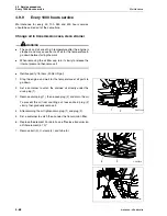
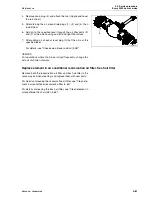
8. Pull out strainer (6).

9. Remove the dirt stuck to strainer (6), then wash in clean die-

sel oil or flushing oil. If strainer (6) is damaged, replace it
with a new part.

10. Install strainer (6), tube (5), and U-clamp (4), then tighten

bolts (3).

Replace O-ring (7) at the strainer portion with a new part,
then install the cover.

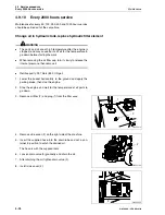
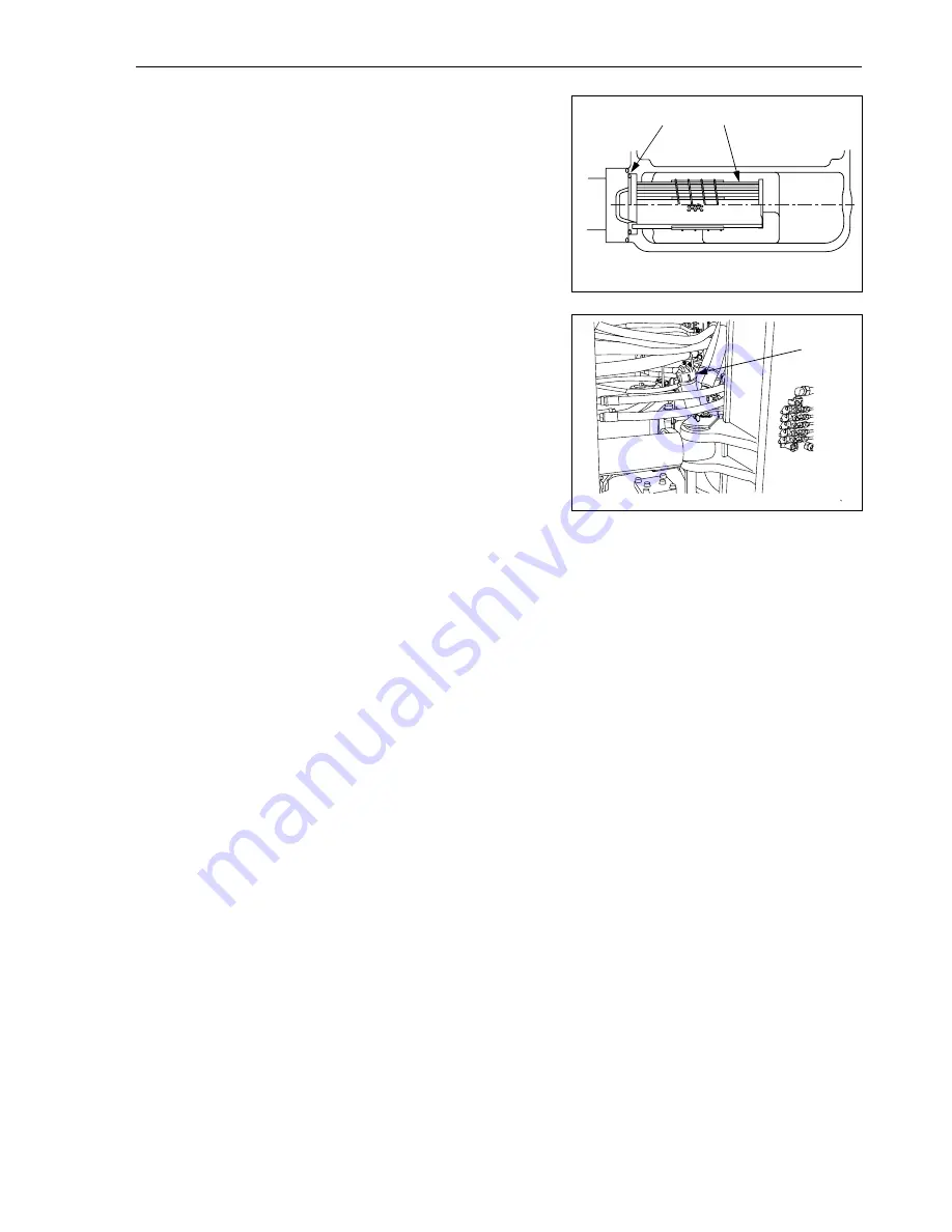
11. Pour in the specified amount of engine oil from oil filler (F).

12. After adding oil, check that the oil is at the specified level. 

For details, see "Check transmission oil level, add oil (4-36)".

13. Check that there is no leakage of oil from the transmission

case or oil filter.

GK050242

7

6

GK050243

F

Summary of Contents for WA500-6H

Page 1: ...should be kept near the machine for reference and periodically reviewed by all personnel who will come into contact with it NOTICE Komatsu has had the operating and maintenance in structions translate...

Page 2: ......

Page 3: ...Foreword WA500 6H VEAM430100 1 1 1 Foreword...

Page 4: ...e that you understand them fully z Keep this manual at the storage location for the Operation and Maintenance Manual given below and have all person nel read it periodically z If this manual has been...

Page 5: ...ructions are observed If you are installing electrical or electronic equipment and or components in the machine and connect them to the vehicle electrical system you must check at own responsibility t...

Page 6: ...used to express the potential level of hazard DANGER Indicates an imminently hazardous situation which if not avoided will result in death or serious injury WARNING Indicates a potentially hazardous s...

Page 7: ...rams show the type of hazardous condition at the top or left side and the method of avoiding the hazardous condition at the bottom or right side In addition the type of haz ardous condition is display...

Page 8: ...ails of the operating procedure see Work possible using wheel loader 3 128 1 3 1 Intended use If you use the machine for any other purpose than specified above we will not accept any responsibility fo...

Page 9: ...1 7 1 3 2 Directions of machine In this manual the directions of the machine front rear left right are determined according to the view from the operator s seat in the direction of travel front of the...

Page 10: ...rea A shows the area where the view is blocked by part of the machine when mirrors or other aids to visibility are installed as standard Please be fully aware that there are places that cannot be seen...

Page 11: ...m your KOMATSU distributor of the following items 1 4 1 Product Identification Number PIN Machine serial no plate and position On the center right of the front frame 1 4 2 Engine serial no plate and p...

Page 12: ...is located on the right inside cab on the rear beam 1 4 4 Axle serial no plate This plate is located on the right of front axle and on the left of rear axle 1 4 5 Transmission serial no plate This pl...

Page 13: ...ered by the bellows 1 4 7 Position of service meter The service meter is displayed on the character display at the bottom center of the machine monitor 1 4 8 Table to enter serial no and distributor G...

Page 14: ...1 10 1 4 6 Seat operator serial no plate 1 11 1 4 7 Position of service meter 1 11 1 4 8 Table to enter serial no and distributor 1 11 1 5 Contents 1 12 1 6 Dimensions weights and operating data 1 19...

Page 15: ...Towing pin 3 77 3 2 8 Backup alarm 3 77 3 2 9 Opening cab window door 3 78 Open lock cancel knob for right cab door 3 78 Cab left door open lock 3 79 Cab left door open knob 3 79 Open lock cancel kno...

Page 16: ...emote boom positioner 3 126 3 3 11 Work possible using wheel loader 3 128 Recommended combination of switches for operation 3 128 Digging operations 3 129 Leveling operation 3 132 Pushing operation 3...

Page 17: ...Towing the machine 3 174 When engine can be used 3 175 When engine cannot be used 3 176 Releasing parking brake 3 176 Emergency travel operation 3 178 3 7 3 If battery is discharged 3 179 Removal and...

Page 18: ...leaner element 4 28 Clean inside of cooling system 4 31 Check transmission oil level add oil 4 36 Check axle oil level add oil 4 38 Clean axle case breather 4 39 Clean air conditioner condenser 4 40 C...

Page 19: ...draulic filter element 4 76 Clean hydraulic tank strainer 4 78 Replace hydraulic tank breather element 4 79 Change axle oil 4 80 Replace element in air conditioner recirculation air filter fresh air f...

Page 20: ...tion mode 6 21 Method of using subtraction mode 6 24 Printout from load meter 6 28 Selection of printout mode 6 29 6 2 Joystick steering system 6 32 6 2 1 Components 6 32 6 2 2 Structure and function...

Page 21: ...20 930 Breakout force hydraulic kN 286 8 Lifting capacity hydraulic on ground kN 348 7 Operating weight kg 31 700 a Reach at 45 discharge mm 1 350 b Dumping height at 45 discharge mm 3 460 c Lift heig...

Page 22: ...rming equipment 1 7 1 CE Conforming equipment CE Conforming equipment 1 2 3 4 5 Type Part No Volume m Load Capacity kg Hydraulic pressure bar Weight kg Bucket WA500 6H 425 71 H2800 5 3 9 540 2 695 425...

Page 23: ...re deemed to have been fulfilled when the manufacturer of the equipment confirms fulfilment of the form 419 93 H1250 along side The certification must be sent to the customer and the wheel loader manu...

Page 24: ...1 7 CE Conforming equipment Foreword 1 22 WA500 6H VEAM430100 GK032014 D1 C1 B1 1 D2 C2 B2 Sh H1 H2 J 2 Sh A2 A1 G d1 d2 3 3 b3 b4 b1 b2 e d2 h c d1 X1 Y1 Y2 X2...

Page 25: ...le vertical D1 Distance headlight centre front axle horizontal D2 Distance headlight centre front axle vertical G Weight of equipment and working load H1 Distance bucket pivoting point bucket upper ed...

Page 26: ...1 7 CE Conforming equipment Foreword 1 24 WA500 6H VEAM430100...

Page 27: ...1 2 Safety WARNING Please read and make sure that you fully understand the precautions described in this manual and the safety labels on the machine When operating or servicing the machine always foll...

Page 28: ...eep them clean When cleaning them use soap and water Do not use organic solvents or gasoline These may cause the safety labels to peel off If the safety labels are damaged or lost or cannot be read re...

Page 29: ...WA500 6H VEAM430100 2 3 2 1 2 Presentation of safety labels 1 2 3 4 5 6 7 8 9 10 11 12 13 14 15 16 GK050308 GK032018 GK032019 GK032020 GK032021 GK032022 GK032023 GK032024 GK032025 GK032026 GK03202 GK...

Page 30: ...fety labels Safety 2 4 WA500 6H VEAM430100 1 2 3 4 5 6 7 8 9 10 11 12 13 14 15 16 GK050308 GK032018 GK032019 GK032020 GK032021 GK032022 GK032023 GK032024 GK032025 GK032026 GK03202 GK032028 GK032030 GK...

Page 31: ...radiator is uncapped while hot Allow coolant to cool before removing cap 8 Precautions when handling battery cable 421 93 H1310 Sign indicates an electric hazard from handling the cable Read manual fo...

Page 32: ...ine during operation or maintenance noise vibration smell incorrect gauges smoke oil leakage etc or any abnormal display on the warning devices or monitor report to the person in charge and have the n...

Page 33: ...r sons that you need to contact in an emergency Safety features z Be sure that all guards and covers are in their proper posi tion Have guards and covers repaired immediately if they are damaged z Und...

Page 34: ...m partment when driving or operating the machine z Never bring any dangerous objects such as flammable or explosive items into the operator s compartment Always apply lock when leaving operator s seat...

Page 35: ...ne check the handrails and steps and if there is any oil grease or mud on them wipe it off immediately In addition repair any damage and tighten any loose bolts z Do not get on or off the machine whil...

Page 36: ...levers by mistake the gap between the work equipment and machine and between the cylinder and work equipment will change and you your hand or arm will be caught and you may suffer serious injury If yo...

Page 37: ...rk on the chas sis move any flammable materials to a safe place before starting When washing parts with oil use a non flammable oil Diesel oil and gasoline may catch fire so do not use them Put greasy...

Page 38: ...fire occurs escape from the machine as follows z Turn the start switch OFF to stop the engine z Use the handrails and steps to get off the machine Window washer liquid Use an ethyl alcohol base washer...

Page 39: ...lead to serious personal injury Modifications may have an adverse effect on items such as machine strength and visibility Before making a modification consult your KOMATSU distribu tor KOMATSU will n...

Page 40: ...Before starting work near electric cables inform the local power company of the work to be performed and ask them to take the necessary action z Even going close to high voltage cables can cause elec...

Page 41: ...operator should pay careful attention to the signs and follow the instructions of the signalman z Only one signalman should give signals z When working in dark places turn on the working lamp and fron...

Page 42: ...he door on the other side Be careful about asbestos dust Asbestos dust in the air can cause lung cancer if it is inhaled There is danger of inhaling asbestos when working on jobsites handling demoliti...

Page 43: ...of the air cleaner and check for damage to the electric wiring z Check that there is no mud or dust accumulated around the movable parts of the accelerator pedal or brake pedal and check that the ped...

Page 44: ...machine z For machines equipped with a back up alarm check that the alarm works properly Precautions in cold areas z Carry out the warming up operation thoroughly If the machine is not thoroughly war...

Page 45: ...Before travelling check again that there is no one in the sur rounding area and that there are no obstacles z Before travelling sound the horn to warn people in the area z Always operate the machine...

Page 46: ...to the ground and travel at low speed Never travel over obstacles which make the machine tilt strongly to one side z When traveling or carrying out operations always keep a safe distance from people s...

Page 47: ...fallen leaves or wet steel plates with low speed Even with slight slopes there is a hazard that the machine may slip z If the engine stops depress the brake pedal immediately lower the bucket to the...

Page 48: ...ions on a downhill slope An excessive load will be brought to bear on the machine and this will cause damage to the machine z It is dangerous to use the bucket or lift arm for crane opera tions so do...

Page 49: ...will suddenly increase so be sure to reduce the speed z When the bucket is fully loaded never start turn or stop the machine suddenly There is danger of the machine turning over z When handling unsta...

Page 50: ...y careful when working on slopes z With frozen ground surfaces the ground becomes soft when the temperatures rises and this may cause the machine to tip over z If the machine enters deep snow there is...

Page 51: ...rking brake switch 2 to the ON position then stop the engine z Lock all points that can be locked and store the key in a safe place z When parking the machine on public roads ensure that it does not o...

Page 52: ...ide a safe loading slope Take suitable steps to prevent the ramps from moving out of position or coming off z Be sure the ramp surface is clean and free of grease oil ice and loose materials Remove di...

Page 53: ...sing over bridges or structures on private land check first that the structure is strong enough to support the weight of the machine When traveling on public roads check first with the relevant author...

Page 54: ...h the area with large amount of water z If acid gets into your eyes flush them immediately with large amount of water and seek medical attention z Before working with batteries turn the starting switc...

Page 55: ...ne and problem machine There is a hazard that the machine will move when the power is connected z Be sure to connect the positive cable first when installing the booster cables Disconnect the negative...

Page 56: ...ng is ample for the weight of the towed machine z Never use a wire rope which has cut strands A reduced diameter B or kinks C There is danger that the rope may break during the towing operation z Alwa...

Page 57: ...while you are performing service or main tenance you could suffer serious injury or property damage Keep work place clean and tidy Do not leave hammers or other tools lying around in the work place Wi...

Page 58: ...engine turn the starting switch to the ON position operate work equipment control lever 1 fully in the RAISE and LOWER directions 2 3 times to release the remaining pressure in the hydraulic circuit...

Page 59: ...ain contact with the other workers z When carrying out operations near the fan fan belt or other rotating parts there is a hazard of being caught in the parts so be careful not to come close z Never d...

Page 60: ...es surised nitrogen Do not open or damage the pressure accumu lator The accumulator is charged with high pressure nitrogen gas When handling the accumulator careless procedure may cause an explosion w...

Page 61: ...tand under it z The boom must be secured against moving if any work is to be carried out under it when it is in a raised position For this purpose you should use a supporting prop 1 which is to be pos...

Page 62: ...ieces might be sent flying and injure people in the sur rounding area Always check that there is no one in the surrounding area z There is a hazard that the pin hit with strong force may fly out and i...

Page 63: ...wet so check for cracks in the piping and hoses and for swelling in the hoses When carry out inspection wear safety glasses and leather gloves z There is a hazard that high pressure oil leaking from...

Page 64: ...o the outer layer through to the intermediate layer brittleness in the outer layer distortions in pressurised or unpressurised state not con forming with the original shape of the installed hose leaka...

Page 65: ...tective equipment Periodic replacement of safety critical parts z In order for the machine to be operated safely for a long time it is necessary to add oil and to carry out service and maintenance at...

Page 66: ...o not let off pressure when the pressure in a warm tyre has increased z Do not light a fire and do not carry out welding near the tyre z Keep the working area free of pointed or sharp objects that may...

Page 67: ...Operation WA500 6H VEAM430100 3 1 3 Operation WARNING Please read and make sure that you understand the SAFETY section before reading this section...

Page 68: ...1 General view of machine 1 Bucket 8 Turn signal lamp 2 Tilt lever 9 Head lamp 3 Front wheel 10 Lift cylinder 4 Bucket cylinder 11 Lift arm 5 Front working lamp 12 Rear working lamp 6 ROPS cab 13 Rea...

Page 69: ...h panel left 18 Lift arm control lever 6 Directional lever 19 Hold switch 7 E C S S switch Option 20 Bucket control lever 8 Horn button 21 Load meter sub total switch Option 9 Hazard lamp switch 22 St...

Page 70: ...selector switch Option 2 Load meter mode selector switch Option 3 Character display mode selector switch 4 Character display item selector switch 5 E C S S switch Option 6 Parking brake switch 7 Fron...

Page 71: ...t switch 5 Remote positioner raise lower set switch 6 Remote positioner bucket angle set switch 7 RPM set ON OFF switch 8 RPM set idling up down selector switch 9 Starting switch 10 Cooling fan revers...

Page 72: ...VEAM430100 Overhead portion Right overhead portion Rear of operator s seat 1 Cassette stereo with AM FM radio Option 4 Emergency parking brake cancel switch 2 Air conditioner control panel 3 Rear hea...

Page 73: ...lever position pilot lamp 11 Modulation clutch temperature caution lamp 33 Torque converter oil temperature gauge 12 Cooling fan reverse rotation pilot lamp 34 Torque converter oil temperature cautio...

Page 74: ...caution lamps and pilot lamps light up for 2 seconds to check the system After the alarm buzzer sounds for 2 seconds it goes off if the condition is normal The shift indicator display shows 88 for 2 s...

Page 75: ...ay 1 REMARK The alarm buzzer sounds in a 1 6 second cycle 0 8 sec ON 0 8 sec OFF The same cycle for ON OFF Caution This warning is given if the cooling water or lubricating oil over heat The central w...

Page 76: ...nitor lights up and at the same time action code E01 is displayed on character display 1 In the case of this warning the central warning lamp does not light up and the alarm buzzer does not sound Cent...

Page 77: ...is reached after completion of the system check with the starting switch at the ON position the maintenance monitor caution lamps flash or light up and at the same time the filter or oil to be replac...

Page 78: ...arting switch is OFF the time is displayed on the bottom line if the top portion of the character display mode selector switch is kept pressed 3 Action code display WARNING If action code E03 is displ...

Page 79: ...r repairs REMARK The top line of the character display displays E02 and the bot tom line displays the condition of the machine related to over heating E01 When a failure occurs in the mechanical syste...

Page 80: ...displayed with the first 6 digits on the left side of the character display The code displayed after the space on the right side of the failure code indicates the controller that detected the failure...

Page 81: ...on the char acter display if an action code is being displayed If there are two or more items to be displayed they are dis played repeatedly in turn If there are more than 10 items all the items are...

Page 82: ...ssion oil Change oil in transmission case clean strainer 4 68 z Corrosion resistor Replace corrosion resistor cartridge 4 75 z Hydraulic tank breather element Replace hydraulic tank breather element 4...

Page 83: ...emergency stop items the alarm buzzer will sound intermittently and the lamp for the loca tion of the abnormality and the central warning lamp will light up At the same time E03 CHECK RIGHT NOW is dis...

Page 84: ...n if the oil pressure drops further the parking brake is auto matically actuated Immediately after the engine starts the accumulator is in the process of storing pressure so the brake oil pressure cau...

Page 85: ...the same time E03 CHECK RIGHT NOW is displayed on the character display so stop the machine immediately then stop the engine and carry out inspection 4 Steering oil pressure caution lamp Red This lamp...

Page 86: ...p operations quickly and carry out the following action 1 Axle oil temperature caution lamp 2 Torque converter oil temperature caution lamp 3 Engine coolant temperature caution lamp 4 Hydraulic oil te...

Page 87: ...lector switch down one range to reduce the travel speed 2 Avoid using the brake 3 Do not keep the brake pedal depressed continuously use the brake only intermittently If use of the brake is reduced fo...

Page 88: ...out 4 Hydraulic oil temperature caution lamp This lamp 4 lights up to warn the operator that the hydraulic oil temperature has risen During checks before starting when the starting switch is turned to...

Page 89: ...Operation 3 2 Explanation of components WA500 6H VEAM430100 3 23 6 Modulation clutch temperature caution lamp This lamp 6 is not active GK050029...

Page 90: ...ons quickly and carry out the following action 1 Radiator coolant level caution lamp 2 Engine oil level caution lamp 3 Battery electrolyte level caution lamp Option 4 Maintenance caution lamp 5 Air cl...

Page 91: ...ed so stop the engine check the water level in the radiator sub tank and add water 2 Engine oil level caution lamp This lamp is not active 3 Battery electrolyte level caution lamp Option This lamp 3 l...

Page 92: ...nt see Filter oil replacement time display 3 15 After replacing the filter or changing the oil reset time for the replacement For details see Reset method for filter oil replacement time 3 38 5 Air cl...

Page 93: ...ion oil filter is clogged the transmission clogging caution lamp lights up At the same time E01 TRANSM FILTER is displayed so stop the engine and replace the element REMARK If the engine is stopped or...

Page 94: ...ency steering pilot lamp 4 Output mode pilot lamp power mode 5 Preheating pilot lamp 6 Auto greasing pilot lamp 7 Joystick pilot lamp Option 8 Shift indicator 9 Auto shift pilot lamp 10 Lockup pilot l...

Page 95: ...ights up At the same time COOLING FAN REVERSE is displayed on the character display For details see Cooling fan reverse rotation switch 3 62 REMARK When the engine is running even if the cooling fan r...

Page 96: ...ghts up and when the preheating is com pleted it goes out The preheating time differs according to the engine water tem perature For details see Starting engine 3 108 6 Auto greasing pilot lamp This l...

Page 97: ...L to give different shift points For details see Transmission auto shift manual shift selector switch 3 58 10 Lockup pilot lamp Option This lamp 10 shows that the torque converter has entered the lock...

Page 98: ...If there is a disconnection in the turn signal lamp the flashing interval becomes shorter 14 Head lamp high beam pilot lamp This lamp 14 lights up when the head lamp is at high beam When the dimmer sw...

Page 99: ...peration It does not light up when the setting is power mode This lamp is interconnected with the accelerator pedal and lights up or goes out according to the operation of the accelerator pedal so use...

Page 100: ...ration 3 34 WA500 6H VEAM430100 Meter display portion 1 Torque converter oil temperature gauge 2 Engine cooling water temperature gauge 3 Hydraulic temperature gauge 4 Fuel gauge 5 Load meter Option 6...

Page 101: ...he character display Run the engine under no load at a mid range speed and wait until the indicator returns to the green range 3 Hydraulic temperature gauge This meter 3 indicates the hydraulic oil te...

Page 102: ...his display 5 shows the amount that is loaded For details see Handling load meter 6 2 6 Speedometer This display 6 shows the travel speed or engine speed For details of the method of switching the dis...

Page 103: ...ssed the screen changes to LOAD METER To return from each menu to the standard menu press the of the character display mode selector switch OVERALL MENU Standard screen service meter display or warnin...

Page 104: ...tarting switch OFF Reset method for filter oil replacement time The filter and oil replacement time is displayed on the character display so if the filter and oil have been replaced reset the filter a...

Page 105: ...turn 6 When resetting the replacement interval press the or portion of the character display item selector switch set the cursor on YES then press the portion of the character display mode selector s...

Page 106: ...er will be displayed next time 4 The telephone number can be displayed up to 12 digits Input in order starting from the first digit on the left The cursor is displayed at the input position Press the...

Page 107: ...the character display mode selector switch The presently selected language is displayed 4 Press the or portion of the character display item selector switch to select the desired language NOTE The av...

Page 108: ...arately for the monitor overall excluding the liquid crystal display and for the liquid crystal display LCD If it is desired to adjust only the liquid crystal display LCD press the or of the character...

Page 109: ...t the clock will show the correct time from that time on 5 Input the time The cursor is displayed in turn at the input position for the date and time Press the or portion of the character display item...

Page 110: ...f the character display mode selector switch is pressed the screen displays LOAD METER If the or portion of the character display item selector switch is then pressed the display changes to ODO odome...

Page 111: ...ys LOAD METER If the or portion of the character display item selector switch is then pressed the display changes to ODO odome ter 2 Press the or of the character display item selector switch to displ...

Page 112: ...switch Option 16 Lamp switch 5 Load meter mode selector switch Option 16 Turn signal lever 6 Character display mode selector switch 16 Dimmer switch 7 Character display item selector switch 17 Load m...

Page 113: ...ctor switch Option 24 Transmission cut off set switch 33 Engine power mode selector switch 25 Remote positioner raise lower set switch 34 Rear heated wire glass switch 26 Remote positioner bucket angl...

Page 114: ...ine is started the preheating pilot lamp will light up automati cally and preheating will start The preheating time differs according to the water temperature when the engine is started If the preheat...

Page 115: ...to switch the load meter display When the switch is released it automatically returns to its origi nal position The switch is operated as follows Position a Use this position when switching to total l...

Page 116: ...Position Press here to cancel each mode or operation 7 Character display item selector switch This switch 7 is used to switch the function of the character dis play When the switch is released it auto...

Page 117: ...irst lower the work equipment to the ground then turn the E C S S switch OFF before starting the inspection and maintenance operation z When carrying out leveling work turn the E C S S switch OFF REMA...

Page 118: ...h WARNING Use the hazard lamp only in emergencies Using the hazard lamp when traveling may cause confusion for other machine operators This switch 10 is used in emergencies such as when the machine br...

Page 119: ...switch 11 operates the parking brake Position a ON The parking brake is applied and the parking brake pilot lamp lights up Position b OFF The parking brake is released REMARK If the directional lever...

Page 120: ...arance lamp or head lamp the working lamp will not light up 13 Rear working lamp switch WARNING Always turn the working lamp off before traveling on public roads When turning the rear working lamp ON...

Page 121: ...earance lamps tail lamps and instrument panel light up Position c Head lamps light up in addition to lamps at b position REMARK The lamp switch can be operated regardless of the position of the lever...

Page 122: ...he travel speed is below 12 5 km h 7 8 MPH in any speed range when traveling in either forward or in reverse the kick down switch is actuated and it is possible to shift down to 1st This makes it easy...

Page 123: ...or operate the transmission shift mode selector switch to MANUAL It is also possible to cancel the hold shift by turning the starting switch OFF 20 Load meter subtotal switch Option It is possible to...

Page 124: ...slope set the trans mission cut off switch to the OFF position depress the accelera tor pedal while keeping the left brake pedal depressed then gradually release the brake pedal and allow the machine...

Page 125: ...ick out position for the lift arm Position a When the lift arm is above the horizontal position raise the lift arm to the position to set the kick out Press the top a of this switch to set the kick ou...

Page 126: ...lay shows 5 up and 5 down Each time remote positioner bucket angle set switch a or b is pressed the display changes 1 or 1 and the buzzer emits short sounds When operation of the switch is stopped at...

Page 127: ...OFF the idle up or idle down speed data in memory are cleared When setting again start the procedure from the begin ning To actuate this switch check that the RPM set ON OFF switch is at the ON positi...

Page 128: ...rse Position b OFF The cooling fan is set to rotate in the normal direction Stop the engine before operating the switch Switching normal rotation reverse rotation With the engine stopped do as follows...

Page 129: ...en light loads such as blasted rock are being handled and the bucket tilt operation is carried out continuously N position Semi auto digging is switched OFF At positions a and b the pilot lamp inside...

Page 130: ...ge is maintained until the travel speed is reduced to the condition for shifting gear When the actual travel speed range is 2nd 4th in both forward and reverse the torque converter lock up function is...

Page 131: ...utput is provided accord ing to the amount of the accelerator pedal is depressed Use this particularly when the work must be completed in a short cycle time Even if the engine is stopped in power mode...

Page 132: ...ease the parking brake Please contact your KOMATSU distributor to have the brake released Position a Release Position b Normal position 37 Room lamp switch The switch 37 is used to turn the room lamp...

Page 133: ...Directional lever 3 Gearshift lever stopper 4 Work equipment lock lever 5 Bucket control lever 6 Lift arm control lever 7 Brake pedal 8 Accelerator pedal 9 Handle for adjusting fore and aft position o...

Page 134: ...d 4th REMARK The length of the lever can be adjusted to 3 stages positions A B C To adjust the length remove the screw E at the bottom of the lever knob D slide the knob to the desired posi tion then...

Page 135: ...rter is locked up the lock up is cancelled To set to the desired speed range when traveling uphill or down hill or when carrying out grading do as follows z When fixing the speed range Press the HOLD...

Page 136: ...t the LOCK position and work equip ment control lever is touched by mistake it may lead to a serious accident z If the work equipment lock lever is not placed securely at the LOCK position the work eq...

Page 137: ...on from near the horizontal position the lever also does not stop at the detent position 6 Lift arm control lever This lever 6 is used to operate the lift arm Position a RAISE When the lever is pulled...

Page 138: ...ke pedal for normal braking operations Left brake pedal The left brake pedal operates the wheel brakes When the transmission cut off switch is in the ON position and if this brake pedal is depressed w...

Page 139: ...hine and set the work equipment lock lever to the LOCK position With this handle 9 is possible to move the work equipment con trol lever right console to the front or rear within range a of 180 mm 7 i...

Page 140: ...ious accident or personal injury This lever is used to unlock and lock the steering column when adjusting the position of the steering column to the front or rear or up or down F FREE position Steerin...

Page 141: ...ap until tight then insert the key into the key slot 2 Turn the key counterclockwise and take the key out Method of opening and closing cap with lock for the hydraulik tank filler port To open the cap...

Page 142: ...removed the steering wheel cannot be used for steering and this may lead to serious damage or injury The safety bar is a device to lock the front frame and rear frame so that machine does not articula...

Page 143: ...terweight 2 Use linch pin 3 to set so that the towing pin does not come out Reverse this operation to remove the pin 3 2 8 Backup alarm This sounds an alarm when the directional lever is set to the R...

Page 144: ...he right window of the cab insert lock release knob 1 into catch 2 then lower the lock release knob If the door is closed with the lock release knob already lowered the lock release knob may be broken...

Page 145: ...tch 1 to lock it in position 2 When attaching the door in position lock it firmly to the catch 3 When getting on or off the machine hold the handrail on the inside 4 When closing the door from the ope...

Page 146: ...ob 1 There are 3 points for lock position A 3 2 10 Handling cab wiper Preventing damage to wiper arm bracket NOTE When angling the wiper arm 1 to the front check that the wiper blade is hanging free W...

Page 147: ...ned After cleaning press the reset button to cancel the lamp For details of the method of cleaning see Cleaning or replacing outer element 4 29 3 2 12 Fuse NOTE Before replacing a fuse be sure to turn...

Page 148: ...ir conditioner blower 11 5A Air conditioner compressor 12 20A Rear heated wire glass 13 10A Car radio Auto greasing 14 20A Air suspension seat 12V converter 15 10A KOMTRAX 1 2 3 4 5 6 7 8 9 10 11 12 1...

Page 149: ...ng 24V as the power source for 12V equipment will cause failure of the equipment z When using the electric power source do not install any equipment which will exceed the maximum amperage When cigaret...

Page 150: ...oner ON OFF When the switch is turned ON the air conditioner monitor dis plays the setting being used when the switch was previously turned OFF 2 Fan switch This switch 2 can be used to adjust the air...

Page 151: ...inside the cab fresh or to remove the mist from the cab windows When the air conditioner takes in fresh air from the outside the pressure inside the cab rises and this prevents the entry of dirt The...

Page 152: ...for a long time with the air condi tioner set to the lowest temperature and minimum air flow there is danger that the receiver drier may freeze z If it freezes and no cold air comes out stop using th...

Page 153: ...et to FRESH 5 Press air conditioner switch 5 to operate the cooling REMARK If the ambient temperature is below 0 C 32 F the air condi tioner cooling may not work In this case set to RECIRC and warm up...

Page 154: ...onditioner z If you smoke when using the cooling your eyes may sting If this happens switch temporarily to cooling and ventilation to remove the smoke z When using the air conditioner for a long perio...

Page 155: ...temperature to a medium temperature For details of the method for cleaning the air filter and inspecting the refrigerant see Clean element in air conditioner fresh air fil ter 4 54 Clean element in a...

Page 156: ...to the handrails and steps and tighten any loose bolts Failure to do this may cause workers to fall and suffer serious personal injury If the machine is at an angle reposition it level before checking...

Page 157: ...ose bolts on handrail and steps Repair any damage and tighten any loose bolts 8 Check for damage to gauges lamps on instrument panel and loose bolts Check for damage to the panel gauges and lamps If a...

Page 158: ...o which the machine is articulated Using the step in the center of the front frame to move to the opposite side from the side which is articulated is extremely dangerous Do not do this When cleaning t...

Page 159: ...or with stepped type wear Damage Tires with damage which has reached the cords or with cracks in the rubber Tires with cut or pulled cords Tires with peeled separated surface Tires with damaged bead L...

Page 160: ...sec If the lamps do not light up there is probably a failure or dis connection Contact your KOMATSU distributor for inspec tion Check dust indicator 1 If air cleaner clogging caution lamp 1 on the ma...

Page 161: ...d display to its original position Drain water from fuel pre filter 1 Check if any water is accumulated in cap 1 at the bottom of the filter 2 If there is water accumulated in the cap 1 loosen drain p...

Page 162: ...release the pressure before removing it CAUTION When adding coolant use the step and handrail provided and support your body securely 1 Check that the cooling water level is in the range between the...

Page 163: ...g when the engine is stopped ENGINE STOPPED and the other side gives the levels for when the engine is idling ENGINE IDLING When measuring the oil level measure with the engine stopped and use the sid...

Page 164: ...k of fuel If the engine has run out of fuel the air bleeding operation can be carried out more quickly if the fuel tank is completely filled with fuel 1 Turn the engine starting switch to the ON posit...

Page 165: ...oler and can extend the cleaning interval Method of rotating fan in reverse NOTE z When the engine is running even if the cooling fan reverse rotation switch is operated the fan will not rotate in rev...

Page 166: ...operations if the fan is rotated in reverse the flow of air is from the rear of the machine to the engine and this blows out the dirt from the radiator fins 7 Run the engine at high idle Select the t...

Page 167: ...line for the spray pressure is 9 8 MPa 100 kgf cm2 1420 PSI With a nozzle diameter of 2 mm 0 1 in keep at least 100 mm 3 9 in away REMARK Steam or water can be used instead of compressed air 12 After...

Page 168: ...there is any accumulation of flammable material around the bat tery and remove such flammable material Please contact your KOMATSU distributor for investigation and correction Check parking brake Che...

Page 169: ...l adjustment Lift lever and move seat forwards backwards Release the lever to lock the seat B Height and Slope adjustment Pull lever and adjust the seat position in height and slope by loading unloadi...

Page 170: ...safety belt before you start work and do not take it off during work Put on the safety belt in such a way that it is not twisted and fits tightly The machine is provided with a lap belt which automati...

Page 171: ...annot secure the visibility and may be injured or may injure someone seriously Range of view X right 2000mm 6 ft 7 in Range of view Y left 2000mm 6 ft 7 in Range of view Z room 1500mm 4 ft 11 in Mirro...

Page 172: ...or personal injury 1 Check that parking brake switch 1 is at the ON position A 2 Check that directional lever 2 is at the N position If directional lever 2 is not set to the N position the engine wil...

Page 173: ...ition before starting the engine monitors gauges and central warning lamp light up for approx 2 seconds and the alarm buzzer sounds for approx 2 sec If any monitor does not light up there is probably...

Page 174: ...ts may be damaged z Do not keep the starting motor rotating continuously for more than 20 seconds If the engine does not start wait for at least 2 minutes before trying to start the engine again Avoid...

Page 175: ...ime To prevent this release the accelerator pedal z The turbocharger rotates at extremely high speed Immedi ately after the engine is started the pressure of the lubricat ing oil has not risen suffici...

Page 176: ...hydraulic oil temperature is low do not carry out oper ations under heavy load or at high speed There is danger that the pump may be broken Breaking in the machine CAUTION Your KOMATSU machine has bee...

Page 177: ...tes 3 In cold weather only carry out the following operation to warm up the hydraulic oil After carrying out the warming up operation check that the engine rotation is smooth then set work equipment l...

Page 178: ...uptly stopped before it has cooled down engine life may be greatly shortened Consequently do not abruptly stop the engine except for an emergency In particular if the engine has overheated do not abru...

Page 179: ...ot allow people to get near the machine z Clear the machine s travel path of any obstacle z Pay particular attention to the blind spot at the rear of the machine when traveling in reverse z When start...

Page 180: ...n A then turn it OFF position B again 5 Set to the desired speed range position Set the speed range position as follows A Use transmission auto shift manual shift selector switch 7 to select auto shif...

Page 181: ...ackup alarm does not sound please contact your KOMATSU distributor for repairs 7 Release right brake pedal 5 then depress accelerator pedal 10 to move the machine REMARK When starting off up a slope t...

Page 182: ...th a kickdown switch 3 that shifts the gear down to 1st if the button at the tip of the lift arm control lever is pushed when the machine is traveling in 2nd gear We recommend the use of the kickdown...

Page 183: ...travel Max speed for changing direction 12 km h 7 5 MPH There is no need to stop the machine even when switching between FORWARD and REVERSE Place directional lever 1 in the desired position Position...

Page 184: ...hanging the travel direction Changing the direction of travel at high speed will have an adverse effect on the durability of the transmission If the direction of travel is changed in area II the alarm...

Page 185: ...k equipment or machine may move suddenly and cause a serious accident Before leav ing the operator s compartment always set the work equip ment lock lever securely to the LOCK position z When the park...

Page 186: ...he same way as the right brake pedal For details of adjusting the brake pedal depression position see Adjusting transmission cut off position 3 121 Raise or lower the pre selected brake pedal depressi...

Page 187: ...ted short sound and the cut off position is set Method of canceling cut off position 5 After the buzzer sounds in Step 4 of the adjustment proce dure the transmission cut off switch flashes for 2 seco...

Page 188: ...steering wheel 1 to turn the machine With this machine the front frame is joined to the rear frame at the center of the machine by the center pin The front and rear frames bend at this point and the r...

Page 189: ...personal injury Always check that the condition is as shown in the diagram z When pulling the work equipment lock lever up or pushing it down be careful not to touch work equipment control lever A Wor...

Page 190: ...s at that position When the lift arm reaches the maxi mum height the lever returns to the HOLD position Bucket operation Set the work equipment lock lever to the FREE position before operating the con...

Page 191: ...ion then return it to HOLD or set the lift arm control lever to the detent position This is taken as the starting signal and semi auto digging will start after approx 1 second During semi auto digging...

Page 192: ...wards the tilt position facing up or dump position facing down operate the remote positioner bucket angle set switch to change the stopping angle of the bucket It is possible to set the angle up or do...

Page 193: ...sition and press the top of the remote positioner raise lower set switch The buzzer will emit short sounds the position is set and the lamp inside the switch lights up Method of checking actuation z R...

Page 194: ...ve fuel efficiency and to increase the service life of the machine we recommend the combination of switches shown in the table below to match the operating conditions GK050129 1 2 3 1 Transmission aut...

Page 195: ...keep the operating jobsite flat and remove any fallen rocks z When working with stockpiles operate the machine in 1st or 2nd gear when loading blasted rock operate the machine in 1st gear 1 When driv...

Page 196: ...cket is thrust too much and the lift arm stops rising or the machine stops moving forward release the accelerator pedal a little Proper operation of the accelerator pedal for each type of the soil is...

Page 197: ...operation should be carried out in 1st gear CAUTION Do not set the bucket facing down more than 8 degrees 1 Set the edge of the bucket facing slightly down CAUTION If the bucket hits the rocks in the...

Page 198: ...o the bucket Move the machine backward while spreading soil from the bucket little by little 2 Go over the spread soil with the bucket teeth touching the ground and level the ground by back dragging 3...

Page 199: ...the method of operation which will give the minimum amount of turning and travel in order to provide the most efficient method for the jobsite WARNING z Always keep the jobsite level When the lift ar...

Page 200: ...ket drive the wheel loader in reverse then turn it to face the dump truck and travel forward to load the dump truck The smaller the turning angle of the wheel loader is the more efficient the operatio...

Page 201: ...If the transmission shifts down when the engine speed is high there will be an excessive load on the engine torque converter transmission axles final drive and the whole power train When shifting dow...

Page 202: ...ground surface is more than 8 when digging or lowering the roadbed there is danger of damage to the work equipment Bucket dump angle when levelling Drive the machine in reverse when carrying out leve...

Page 203: ...o bear on the work equipment Carry out the scooping up operations as follows 1 When thrusting the bucket in raise the lift arm slightly at the same time Ample driving force will work on the front whee...

Page 204: ...a bulldozer or hydraulic excavator Treatment of loosened boulders WARNING Do not use this machine to deal with loosened boulders If the boulder is dropped by mistake when handling it there is danger...

Page 205: ...n the machine is traveling at high speed or when the accelerator pedal is depressed the engine speed is high and if the direction of travel is switched between forward and reverse In this condition an...

Page 206: ...lecting the rocks in an area the length of the machine change the direction of the machine to gather rocks and increase the area of level ground Approaching facing NOTE z When lowering the bucket to t...

Page 207: ...ssion axles final drive and the whole power train z When thrusting the bucket in shift down to 1st If the bucket is thrust in at high speed there will be an impact load on the machine and this will re...

Page 208: ...tly and increase the driving force of the front wheels When doing this do not push in too far REMARK When digging up large rocks in some cases it may be better not to raise the lift arm too high If th...

Page 209: ...At this distance the rolling of the tires can prevent wear to the tires In addition keep an angle b of 60 at the intersection between the straight line from the dilution and the straight line from th...

Page 210: ...res z If there is transmission cut off do not turn the transmission cut off switch to the OFF position and depress the brakes or raise the bucket If the brakes are actuated in this condition heat will...

Page 211: ...In addition there is danger of impact pressure being generated in the hydraulic equipment and causing damage to the hydraulic equipment z When loading the dump truck do not pushed forcibly with the b...

Page 212: ...hing between forward and reverse when the machine is station ary If the steering is operated when the machine is station ary it will cause wear or cuts to the tires 1 Switch to R2 and drive in reverse...

Page 213: ...ravity before turning It is dangerous to turn the machine suddenly on slopes Breaking on downhill slope If the foot brake is used excessively when traveling downhill there is danger that the brake may...

Page 214: ...ce the tires become extremely hot This causes early wear of the tires so it should be avoided as much as possible If the machine must be driven for a long distance take the following precau tions z Fo...

Page 215: ...Operation 3 3 Operation WA500 6H VEAM430100 3 149 z Always travel with the bucket empty z Never put calcium chloride or dry ballast in the tires when traveling...

Page 216: ...sure that there is no one in the surrounding area before starting the operation z When removing the pins do not stand behind the bucket In addition be extremely careful not to put your foot under the...

Page 217: ...cket remove all grease and sand or mud from around the pins pin holes and boss then wash the parts After washing coat the pins and the inside of the pin holes with fresh grease 1 Set cord ring 2 on to...

Page 218: ...se to prevent damage to the dust seal when inserting the bucket hinge pin Use a bucket hinge pin that has a grease hole 6 Install mounting bolt 6 7 Coat the groove of cord ring 2 with grease 8 Move co...

Page 219: ...ps 1 to 7 to install the bucket link pin Assemble a pin that has no grease hole at the bucket link 10 Coat the bucket hinge pin and bucket link pin with grease For details see Lubricating 4 61 For det...

Page 220: ...s may lead to a serious accident Before leaving the operator s com partment always set the work equipment lock lever securely to the LOCK position z When the parking brake switch is turned ON it is da...

Page 221: ...ntrol lever 5 and bucket control lever 6 is at the HOLD position then set the work equip ment lock lever 7 to the LOCK position 3 3 15 Checks after completion of operation 1 Walk around the machine an...

Page 222: ...Locking Always lock the following parts 1 Fuel tank filler cap 2 Engine side cover 2 places 3 Cab door 1 place 4 Engine hood 1 place Air cleaner inspection cover REMARK The starting switch key is use...

Page 223: ...t taking due care Tire pressure Measure the tire pressure before starting operations when the tires are cool If the tire inflation pressure is too low there will be overload if it is too high it will...

Page 224: ...If this is the case please contact an authorised KOMATSU dealer Stockpile operations mean the loading of sand and other loose materials Precautions for using load and carry method When traveling cont...

Page 225: ...p well away from the road shoulder z Use ramps of ample width length thickness and strength and install them securely at an angle of less than 15 When using an embankment compact the fill soil thoroug...

Page 226: ...If the ramp sags appreciably reinforce it with blocks etc 3 Determine the direction of the ramp then slowly load the machine 4 Load the machine correctly in the specified position on the trailer Secu...

Page 227: ...ne Only fas ten the eye hooks of the stay ropes at the marked attachment points 6 Put blocks in front and behind the wheels and secure the machine with chains or wire rope to prevent the machine from...

Page 228: ...nter of the tires If the ramp sags appreciably reinforce it with blocks etc 3 Remove the chains and wire ropes fastening the machine 4 Set the frame lock bar to FREE position 5 Start the engine Warm t...

Page 229: ...n z Never enter the area under or around a raised machine z There is a danger of the machine losing its balance Use the procedure below to set the machine in the proper posture and use the lifting equ...

Page 230: ...of lifting position mark Lifting hooks A are located at 4 places on the machine as shown in the diagram on the right Use only these 4 places when lifting do not use any other places There is a serious...

Page 231: ...ever to the LOCK position 3 Stop the engine check that the area around the operator s compartment is safe then lock with the safety bar so that the front frame and rear frame do not articulate 4 Use w...

Page 232: ...oolant con taining antifreeze that has been drained when repairing the radiator please contact your KOMATSU distributor Anti freeze is toxic so do not let it flow into drainage ditches or spray it on...

Page 233: ...nt temperature drops the capacity of the battery will also drop If the battery charge ratio is low the battery elec trolyte may freeze Maintain the battery charge as close as pos sible to 100 and insu...

Page 234: ...al together with drops of water z Park the machine on hard dry ground If this is impossible park the machine on wooden boards The boards help protect the wheels from being frozen in soil and the machi...

Page 235: ...iately after starting the engine Warming up steering hydraulic circuit Slowly operate the steering wheel to the left and right to warm up the oil in the steering valve Repeat this operation for about...

Page 236: ...z To prevent corrosion be sure to fill the cooling system with Supercoolant AF NAC or permanent type antifreeze den sity between 30 and 68 3 6 2 During storage WARNING If it is unavoidably necessary...

Page 237: ...OMATSU distributor When using the machine after long term storage do as follows before using it z Wipe off the grease from the hydraulic cylinder rods z Add oil and grease to all lubrication points z...

Page 238: ...ir bleed plug 2 at the top of the fuel filter head or the supply pump air bleeder there is still remaining pressure so fuel may spurt out Loosen carefully before opening 1 Loosen plug 1 at the top of...

Page 239: ...ubbles come out with the fuel then tighten air bleeder 4 Tightening torque 4 9 to 6 9N m 0 5 to 0 7kgf m 3 6 to 5 1 lbft NOTE Do not use feed pump 5 supplied with the supply pump 6 Carry out priming a...

Page 240: ...z Towing is for moving the machine to a place where inspec tion and maintenance can be carried out and not for moving it long distances The machine must not be towed for long distances z For details...

Page 241: ...achines on slopes or on the tow road z When towing a machine downhill use a larger machine for towing to provide ample rimpull and braking power or con nect another machine to the rear of the machine...

Page 242: ...operations use two machines of at least the same class as the machine being towed Connect one machine each to the front and rear of the machine being towed then remove the blocks from the tires and to...

Page 243: ...e valve If the pressure in the brake accumulator is high do as follows 1 Turn starting switch to the ON position B 2 Set the emergency parking brake switch to the RELEASE position When doing this chec...

Page 244: ...ere removed and tighten uniformly until they stop This releases the parking brake B Therad hole M12 for releasing Emergency travel operation The normal gear shifting operation is carried out by electr...

Page 245: ...s there is danger that it will cause a spark so be extremely careful z If the terminals are loose there is danger that the defective contact may generate sparks that will cause an explosion z When rem...

Page 246: ...e battery to be charged If the voltage is not selected correctly the charger may overheat and cause an explosion z Connect the positive charger clip of the charger to the positive terminal of the batt...

Page 247: ...is no mistake in the booster cable con nections The final connection is to the engine block of the problem machine but sparks will be generated when this is done so connect to a place as far as possib...

Page 248: ...e sure the clips are firmly connected to the battery termi nals 2 Start the engine of the normal machine and keep it to run at high idling speed 3 Turn the starting switch of the problem machine to th...

Page 249: ...ower the work equipment 1 Turn starting switch to the ON position B 2 Set the work equipment lock lever to the FREE position 3 Operate the lift arm control lever to lower the bucket to the ground 4 Se...

Page 250: ...ernator z Replace Starting motor does not turn when starting switch is turned to START z Defective wiring z Insufficient battery charge z Defective starting motor z Check repair z Charge z Check repai...

Page 251: ...r is stalled for long periods z Engine is overheating z Add or drain oil to specified level See WHEN REQUIRED z Place in correct speed range z Reduce stall time z Check engine Noise generated z Lack o...

Page 252: ...ulic system Bucket lacks lifting power Bucket takes time to go up z Lack of oil z Clogged hydraulic filter z Add oil to specified level See EVERY 100 HOURS SER VICE z Replace cartridge See EVERY 2000...

Page 253: ...t z Replace thermostat seal z Tighten cap or replace packing z Replace Water temperature gauge is in white range below z Defective thermostat z Defective monitor z Replace thermostat z Replace Engine...

Page 254: ...3 7 Troubleshooting Operation 3 188 WA500 6H VEAM430100...

Page 255: ...Maintenance WA500 6H VEAM430100 4 1 4 Maintenance WARNING Please read and make sure that you understand the SAFETY section before reading this section...

Page 256: ...clean oil and grease Also keep the containers of the oil and grease clean Keep foreign materials away from oil and grease Checking for foreign materials in drained oil and on filters After oil is chan...

Page 257: ...do as follows z Check the air cleaner clogging caution lamp more frequently to check the degree of clogging of the air cleaner Clean the air cleaner element more frequently z Clean the radiator core...

Page 258: ...spection and maintenance If you forget carrying out the checks after inspection and mainte nance unexpected problems may occur and this may lead to serious injury or property damage Always do as follo...

Page 259: ...vere conditions high temperature high pres sure and deteriorates with use Always use oil that matches the grade and temperature for use given in the Operation and Maintenance Manual Even if the oil is...

Page 260: ...Mainte nance Manual If the fuel is used at temperatures lower than the specified temperature particularly at temperatures below 15 C 5 F the fuel will solidify If the fuel is used at temperatures hig...

Page 261: ...r such as a river water or well water hard water contains large amounts of minerals calcium magne sium etc and this makes it easier for scale to form inside the engine or radiator Once scale is deposi...

Page 262: ...r dirt sticking in the grease would cause wear of the rotating parts Carrying out KOWA KOMATSU Oil Wear Analysis KOWA is a maintenance service that makes it possible to pre vent machine failures and d...

Page 263: ...ents z Precautions when sampling Make sure that the oil is well mixed before sampling Carry out sampling regularly at fixed intervals Do not carry out sampling on rainy or windy days when water or dus...

Page 264: ...ays use KOMATSU genuine filters 4 2 2 Outline of electric system z It is extremely dangerous if the electrical equipment becomes wet or the covering of the wiring is damaged This will cause an electri...

Page 265: ...parts list The parts in parentheses are to be replaced at the same time See Part No in Parts Book KOMATSU Item Part No Part Name Q ty Replacement frequency Engine oil filter Cartridge 2 EVERY 500 HOUR...

Page 266: ...ist Maintenance 4 12 WA500 6H VEAM430100 1 piece corner tooth Right corner tooth Left corner tooth Bolt Bolt Washer Nut Shim 0 5mm Shim 1 0mm 1 1 2 4 2 6 4 2 Tip tooth Tooth Pin 8 8 Segment edge Edge...

Page 267: ...Use the oil recommended according to the ambient temper ature in the chart below z Specified capacity means the total amount of oil including the oil in the tank and the piping Refill capacity means t...

Page 268: ...IONANDMAINTENANCEMANUAL 425 93 H1180 425 93 H1180 G G 6 6 3 3 3 NUMBERSATTHELEFTSIDEOFTHECHARTINDICATETHE 3 NUMBERSATTHELEFTSIDEOFTHECHARTINDICATETHE NUMBEROFLUBRICATIONPOINTS REFERTOTHEABOVE NUMBEROF...

Page 269: ...DH KOMATSU EO30 DH SAE30DH Transmission case Power train oil Note 2 TO30 TO30 TO10 TO10 Hydraulic system Power train oil TO10 TO10 Hydraulic oil HO46 HM HO46 HM HO MVK HO MVK Engine oil KOMATSU EO10W3...

Page 270: ...r Viscosity 150 C specified by ASTM D4741 must be equal to or higher than 3 5mPa S 3 5cP KOMATSU EOS0W30 and EOS5W40 are the most suitable oils If these oils are not available follow the instruction R...

Page 271: ...and can be used continuously for 2 years or 4000 hours KOMATSU Supercoolant AF NAC is strongly recom mended wherever available When using KOMATSU Supercoolant AF NAC there is no need to use a corrosio...

Page 272: ...oil Maintenance 4 18 WA500 6H VEAM430100 4 4 3 Recommended brands recommended quality for products other than KOMATSU genuine oil When using commercially available oils other than KOMATSU genuine oil...

Page 273: ...Width across flats b mm Tightening torque Target value Service limit N m kgf m lbft N m kgf m lbft 6 8 10 12 14 10 13 17 19 22 13 2 31 66 113 172 1 35 3 2 6 7 11 5 17 5 9 8 23 1 48 5 83 2 126 6 11 8...

Page 274: ...43 4 72 3 22 27 117 7 12 0 86 6 88 3 137 3 9 0 14 0 65 1 101 3 24 32 147 1 15 0 108 5 117 7 176 5 12 0 18 0 86 8 130 2 30 36 215 7 22 0 159 1 176 5 245 2 18 0 25 0 130 2 180 8 33 41 255 0 26 0 188 1 2...

Page 275: ...ult to determine the extent of wear or deterioration at the time of peri odic maintenance Hence it is required to replace them with new ones regardless of their condition after a certain period of usa...

Page 276: ...10 Steering hose steering valve stop valve 2 11 Steering hose orbitrol valve stop valve 2 12 Steering hose orbitrol valve charge valve 1 13 Steering hose orbitrol valve joint to tnak 1 14 Brake hose p...

Page 277: ...ssion oil level add oil 4 36 Check axle oil level add oil 4 38 Clean axle case breather 4 39 Clean air conditioner condenser 4 40 Check window washing fluid level add fluid 4 40 Clean radiator fins wi...

Page 278: ...filter element 4 70 Replace fuel filter cartridge 4 71 Clean transmission case breather 4 73 Wash fuel tank breather 4 74 Lubricating 4 74 Replace corrosion resistor cartridge 4 75 Check of engine ai...

Page 279: ...ecking for loose engine high pressure piping clamps hardening of rubber 4 87 Checking for missing fuel spray prevention cap hardening of rubber 4 88 4 9 12 Every 8000 hours service Replace high pressu...

Page 280: ...he regulations NOTE When transporting a machine from an A regulation area to a B regulation area always replace all the injector assemblies before transporting the machine to the new area Check with y...

Page 281: ...only after the first 50 hours Check for loose wheel hub bolts tighten If wheel hub nuts 1 are loose tire wear will be increased and may cause accidents 1 Check for loose nuts and tighten if necessary...

Page 282: ...ing compressed air there is danger that dirt may be blown around and cause serious injury Always use safety glasses dust mask and other protective equipment Checking If air cleaner clogging caution la...

Page 283: ...MPa 7 kgf cm 99 4 PSI from the inside of the outer element along its folds Then direct the compressed air from the outside along the folds and again from the inside NOTE z After cleaning and drying th...

Page 284: ...dicator may show the 3rd stage Replacing inner element 1 First remove the outer element and then remove the inner element 2 Cover the air connector side outlet side with a clean cloth or tape 3 Clean...

Page 285: ...resistor according to the table below Permanent type antifreeze shall meet the requirements of ASTM D3306 03 Stop the machine on level ground when cleaning or changing the coolant The coolant has the...

Page 286: ...lly better to estimate a temperature about 10 C 18 F lower when deciding the mixing rate The mixing ratio depends on the ambient temperature but it should always be a minimum of 30 by volume antifreez...

Page 287: ...uper coolant AF NAC for the coolant Use tap water to dilute the coolant If river water well water or other such water supply must be used contact your KOMATSU distributor We recommend use of an antifr...

Page 288: ...After draining the water close radiator drain valve 6 and oil cooler drain valve 7 11 Add tap water through radiator water filler 4 12 When the radiator is full start the engine and run it at low idle...

Page 289: ...supercoolant and water see Water and supercoolant mix ratio table 21 Drain the coolant from sub tank 8 then clean the inside of the sub tank 22 Add coolant to sub tank 8 to a point between the FULL an...

Page 290: ...various places and it will be impossible to check the oil level correctly 2 Open the cap of oil filler port F remove dipstick G and wipe the oil off with a cloth 3 Insert dipstick G fully in the oil...

Page 291: ...en heat is balanced in whole transmission as after actual work User operating continuously check during lunch time or check during change of shift Run at idling for at least 15 minutes then leave Chec...

Page 292: ...y out the inspection with the machine on a horizontal road surface If the road surface is at an angle the oil level cannot be checked correctly z A Front z B Rear 1 Stop the machine in a horizontal pl...

Page 293: ...the machine in a horizontal place 2 Stop the engine 3 Remove all mud and dirt from around the breather with a brush 4 After removing the mud or dirt from around the breather remove the breather immer...

Page 294: ...shing with a high pressure washing machine apply the water from a reasonable distance Check window washing fluid level add fluid Check the washing fluid levels in washer tank 1 When the fluid has run...

Page 295: ...r the spray pressure is 9 8 MPa 100 kgf cm 1420 PSI With a nozzle diameter of 2 mm 0 1 in keep at least 100 mm 3 9 in away REMARK Steam or water can be used instead of compressed air 6 Open cleaning c...

Page 296: ...th before they wear down as far as the adapter 1 Raise the bucket to a suitable height then put blocks under the bucket to prevent the bucket from coming down Raise the bucket so that the bottom surfa...

Page 297: ...block then set the center of the bucket bottom on the block 3 After lowering the bucket onto the block stabilize it then stop the engine 4 Remove the bolt and nuts 1 and 2 then remove bucket tooth 3 a...

Page 298: ...ditioner ON OFF switch to the ON position z Set the air flow to the maximum position z Set the temperature to the lowest position z Open the doors and windows fully z Turn the air conditioner switch O...

Page 299: ...rn the starting switch to the OFF position A 2 Remove the slow blow fuse box from the chassis 3 Open covers 1 2 and 3 of the slow blow fuse box Covers 2 and 3 can be removed easily by using protru sio...

Page 300: ...replacing the slow blow fuse turn the starting switch to the OFF position A z Always replace the slow blow fuse with a fuse of the same capacity 1 Turn the starting switch to the OFF position A 2 Open...

Page 301: ...carry out the air bleeding operation correctly Before bleeding the air from the piston pump check that the hydraulic is filled with oil up to the top of the sight gauge If the oil level is low add oil...

Page 302: ...5 Stop the engine 6 Loosen air bleed plug 1 of the hydraulic tank and bleed the air from the hydraulic tank 7 Tighten air bleed plug 1 of the hydraulic tank 8 Check the hydraulic oil level If the oil...

Page 303: ...mpare the up and down movement of the machine during travel when the E C S S switch is ON and when it is OFF If there is no change in the up and down movement of the machine the gas pressure in the ac...

Page 304: ...tire is installed Do not make a fire near the tire Selection of tires WARNING Select the tires according to the conditions of use and the weight of the attachments on the machine Use only specified ti...

Page 305: ...the tire or rim In this case be sure to ask a tire repair shop to carry out repairs Be sure to observe the specified inflation pressure Do not adjust the inflation pressure of the tires just after hig...

Page 306: ...l z Check fuel level add fuel z Clean radiator fins by rotating cooling fan in reverse z Check electric wiring z Check parking brake z Check brake pedal z Check inflation pressure of tires 4 9 5 Every...

Page 307: ...may cause burns Wait for the temperature to go down before starting the work z When removing the oil filler cap turn it slowly to release the internal pressure then remove it 1 Lower the bucket horiz...

Page 308: ...ust mask and other protective equipment If the air conditioner has been used the air filter should be cleaned Stop the air conditioner before cleaning the element 1 Stop the engine 2 Open cover 1 3 Re...

Page 309: ...z When adding distilled water to the battery do not allow the battery electrolyte to go above the MAXIMUM UPPER LEVEL line If the electrolyte level is too high it may leak and cause damage to the pain...

Page 310: ...ectrolyte level from side of battery If it is impossible to check the electrolyte level from the side of the battery or there is no display of the UPPER LEVEL line on the side of the battery check as...

Page 311: ...icarbonate then flush it away with a large amount of water or consult your KOMATSU distributor or battery maker When it is possible to use indicator to check electrolyte level If it is possible to use...

Page 312: ...is approx 15 mm 0 6 in approx 58 8 N 6 kgf Tighten nut 4 to increase the tension of the belt loosen nut 4 to reduce the tension of the belt 2 Tighten bolts 1 2 and nut 3 to secure alternator 5 3 Chec...

Page 313: ...t to increase the tension of the belt 4 Tighten bolt 4 and secure in position with locknut 3 5 Tighten bolt 1 and secure the air conditioner compressor in position 6 Check each pulley for damage wear...

Page 314: ...el ground and lower the work equip ment completely to the ground 2 Apply the parking brake 3 Start the engine run it at a mid range speed for 1 minute then stop the engine 4 Turn the starting switch k...

Page 315: ...frequently 1 Put the work equipment horizontally in contact with the ground then stop the engine 2 Using a grease pump pump in grease through the grease fittings marked by the arrows 3 After greasing...

Page 316: ...rs service Maintenance 4 62 WA500 6H VEAM430100 1 Bucket pin 2 places 2 Bucket link pin 2 places 3 Tilt lever pin 1 place 4 Lift cylinder pin 4 places 5 Steering cylinder bottom end 2 places GK050227...

Page 317: ...0 4 63 6 Dump cylinder rod end 1 place 7 Lift arm pivot pin left 8 Lift arm pivot pin right 9 Dump cylinder bottom pin 10 Lift cylinder pin right 11 Lift cylinder pin left 12 Steering cylinder rod end...

Page 318: ...the chassis 3 Open oil filler F 4 Place a container to catch the oil under drain plug P 5 Loosen drain plug P and drain the oil Be careful not to get oil on yourself 6 Check the drained oil and if th...

Page 319: ...ast 30 seconds after stopping the engine to let the internal pressure go down before replacing the filter z Do not bring fire or sparks near the fuel NOTE z Genuine KOMATSU fuel filter cartridges use...

Page 320: ...1 0 kgf m 7 2 lbft 7 Clean the filter holder 8 Check that cap B is installed to the new filter cartridge then fill with clean fuel NOTE When filling with fuel always use fresh fuel and be careful not...

Page 321: ...o leakage of fuel If the filter car tridge is too loose fuel will also leak from the packing so always tighten to the correct amount 12 Replace the filter cartridge and bleed the air When replacing th...

Page 322: ...ly to release the internal pressure then remove it z Refill capacity 76 liters 20 08 US gal 1 Stop the engine and wait for the temperature at all parts to go down 2 Set a container to catch the draine...

Page 323: ...rt 10 Install strainer 6 tube 5 and U clamp 4 then tighten bolts 3 Replace O ring 7 at the strainer portion with a new part then install the cover 11 Pour in the specified amount of engine oil from oi...

Page 324: ...move drain plug 2 at the bottom of the filter case drain the oil then tighten the plug again 3 Loosen hexagonal portion 4 of case 3 then remove case 3 4 Take out element then clean the inside of the c...

Page 325: ...ability When replacing the filter cartridge always use a genuine KOMATSU part z The common rail fuel injection system used on this machine consists of more precise parts than the conventional injec ti...

Page 326: ...ng surface of the filter cartridge with oil 7 Remove filter cartridge cap B and install to the filter holder 8 When installing tighten until the packing surface contacts the seal surface of the filter...

Page 327: ...se feed pump 6 supplied with the supply pump 16 Carry out priming a further approx 20 times then securely tighten wing nut 4 holding the lever of the priming pump Tightening torque 11 8N m 1 2kg m 8 7...

Page 328: ...3 Remove the breather and fit a cover to the breather mount ing hole to prevent dirt from entering 4 Soak the breather in flushing liquid and wash it 5 Install the breather Lubricating 1 Using a greas...

Page 329: ...e sealing surface of a new cartridge then install it to the filter holder 5 Bring the packing surface into contact with the seal surface of the filter holder then tighten it further approx 2 3 turn 6...

Page 330: ...urn it slowly to release the internal pressure then remove it z Refill capacity 337 liters 89 0 US gal 1 Lower the bucket horizontally to the ground and apply the parking brake then stop the engine 2...

Page 331: ...ecified level For details see Check oil level in hydraulic tank add oil 4 53 17 Run the engine at low idling and extend and retract the steering bucket and lift arm cylinders 4 to 5 times Be care ful...

Page 332: ...tank drain the oil from the tank and clean the strainer 1 Lower the bucket horizontally to the ground and turn the parking brake switch ON 2 Stop the engine and wait for the temperature at all parts t...

Page 333: ...ontally to the ground and turn the parking brake switch ON 2 Stop the engine and wait for the temperature at all parts to go down 3 Remove the cap of oil filler F 4 Remove the snap ring from breather...

Page 334: ...release the internal pressure then remove it carefully Refill capacity front 87 liters 22 9 US gal Refill capacity rear 81 liters 21 4 US gal To prevent the drained oil from coming into contact with...

Page 335: ...at the specified level For details see Check axle oil level add oil 4 38 REMARK For operations where the brake is used frequently change the axle oil at shorter intervals Replace element in air condi...

Page 336: ...ered end of strainer case 3 is on the inside then tighten cap 4 8 Install outlet hose 2 of the PPC circuit strainer to cap 4 9 Install covers 1 at the accumulator mount on the right side of the rear f...

Page 337: ...e alternator rotates smoothly If it does not rotate smoothly please ask your KOMATSU distributor to carry out inspection and repair Check engine valve clearance adjust As special tool is required for...

Page 338: ...ion 5 Check that the area around the machine is safe then turn the starting switch to the ON position set the lift arm control lever to FLOAT position d and lower the work equipment to a point 1 m 3 f...

Page 339: ...g motor The brush may be worn or have no grease on the bearing so contact your KOMATSU distributor for inspection or repair If the engine is started frequently carry out inspection every 1000 hours Lu...

Page 340: ...4 9 Service procedure Every 4000 hours service Maintenance 4 86 WA500 6H VEAM430100 3 Center drive shaft 4 places GK050267...

Page 341: ...dening of any rubber parts If any problem is found the part must be replaced In this case please ask your KOMATSU distributor to carry out the replacement NOTE If the engine continues to be used when...

Page 342: ...e protective parts installed to pre vent fire caused by fuel leaking and spraying out on to high tem perature parts of the engine Check visually that there are no missing caps or loose bolts and feel...

Page 343: ...essure piping clamp Ask your Komatsu distributor to carry out this work Replace fuel spray prevention cap Contact your KOMATSU distributor to have the fuel spray pre vention cap replaced Overhaul star...

Page 344: ...4 9 Service procedure Every 12000 hours service Maintenance 4 90 WA500 6H VEAM430100...

Page 345: ...Technical Data WA500 6H VEAM430100 5 1 5 Technical Data...

Page 346: ...clearance mm ft in 450 1 6 F Bucket width cutting edge width mm ft in 3 400 11 2 G Clearance Tip of bucket mm ft in 3 295 10 10 BOC mm ft in 3 395 11 2 H Reach Tip of bucket mm ft in 1 400 4 7 BOC mm...

Page 347: ...Technical Data 5 1 Technical data WA500 6H VEAM430100 5 3 GK032301 A B H I G C E F D...

Page 348: ...have an influence on the noise emission levels 5 3 Vibration level When used for its intended purpose levels of vibration for the earth moving machine transmitted from the operator s seat are lower th...

Page 349: ...se a seat that meets ISO 7096 and keep the seat main tained and adjusted Adjust the seat and suspension for the weight and size of the operator Wear seat belt Inspect and maintain the seat suspension...

Page 350: ...wing guidelines can be effective to minimize risks of low back pain Operate the machine only when you are in good health Provide breaks to reduce long periods of sitting in the same posture Do not jum...

Page 351: ...calculated value This states the angle at which the machine at rest can stand on a slope without tipping over You must not work with the machine at these angles as the motor transmission hydraulic sys...

Page 352: ...5 4 Limit values for slopes Technical Data 5 8 WA500 6H VEAM430100...

Page 353: ...Attachments Options WA500 6H VEAM430100 6 1 6 Attachments Options WARNING Please read and make sure that you understand the SAFETY section before reading this section...

Page 354: ...ad remaining to the target load can be dis played from 0 1 tons to a maximum of 99999 tons but up to 9999 9 tons the digit shown after the decimal point displays the load in units of 100 kg When the l...

Page 355: ...ode see Setting subtrac tion mode 6 9 The load meter can divide the type of material being handled into five categories It can save to memory the total load or the load remaining to the target load fo...

Page 356: ...m an angle below 30 no measurement is carried out until the lift arm reaches 30 If the lift arm is operated RAISE STOP RAISE AGAIN this is judged as one load and no measurement is carried out when the...

Page 357: ...5 3 5 seconds the measurement is carried out twice if it continues for more than 3 5 seconds the mea surement is carried out three times The final calculation is the average of the measurements The m...

Page 358: ...t the load calibration in the same posture as when carrying out actual operations z Warming up Carry out warming up to set the hydraulic oil temperature to the normal working range then carry out norm...

Page 359: ...ed changes during the measure ment the lift arm cylinder pressure also changes and the accuracy of the measurement becomes poor In the mea surement range 30 and above keep the lift arm speed constant...

Page 360: ...ctor switch A B to select the category of load material This completes the setting of the addition mode Calculation starts REMARK When the load meter is set to the addition mode even when the starting...

Page 361: ...r switch to input the target load The character display before input displays 00000 0t and the cursor is on the 10000 digit REMARK The portion of the character display mode selector switch is used to...

Page 362: ...10000 digit to the 1000 digit 2 Press the portion of the character display mode selector switch Accept 0 for the 1000 digit for the target load on the character display The cursor then moves from the...

Page 363: ...or the 100 digit for the target load on the character display The cursor then moves from the 100 digit to the 10 digit 5 The value for the 10 digit the 1 digit and the first place of decimal stays as...

Page 364: ...out 2 Press the load meter mode selector switch A B Each time the switch is pressed MATERIAL changes from A B C D E A When this happens the load for the category of material dis played in MATERIAL is...

Page 365: ...to the normal service meter and clock display REMARK If the display for the category of material on the load meter is A B C D E all lamps light up all the total load data are cleared If top of the lo...

Page 366: ...lay LOAD METER on the character display 3 Use the portion of the character display mode selector switch and the or portion of the character display item selector switch to display OFF on the character...

Page 367: ...et load for each category The load material category is displayed from A to E on the bot tom line of MATERIAL 1 on the load meter 1 Press the load meter mode selector switch A B Each time the switch i...

Page 368: ...raising and lowering the lift arm for at least 10 minutes preferably more than 30 minutes 2 Set so that the character display shows the normal service meter and clock display 3 Press the portion of t...

Page 369: ...accelerator pedal to the same angle as for actual operations Do not change the angle of the accelera tor pedal Always keep it constant To make the lift arm RAISE speed constant carry out at the lift...

Page 370: ...n 30 minutes Load the bucket with a known weight Be careful that the center of gravity of the load does not change when raising or lowering the lift arm 2 Set so that the character display shows the n...

Page 371: ...the lift arm to the maximum height at the same speed as for actual operations Depress the accelerator pedal to the same angle as for actual operations Keep the accelerator angle constant and do not c...

Page 372: ...dard service meter and time is displayed on the character display 2 Press the portion of the character display mode selector switch to display LOAD METER 3 Press character display mode selector switch...

Page 373: ...as an example 2 Fill the bucket with the first load tilt the bucket fully raise the lift arm above the horizontal position then load the dump truck Let us take the load as 5 1t The display shows the b...

Page 374: ...he load meter cancel switch The measurement is cancelled and the total load display returns to 5 1 It is possible to cancel the measurement 15 seconds after the load is displayed or before measuring t...

Page 375: ...urns to the initial condition REMARK To reset keep the load meter sub total switch pressed for at least 2 seconds When printer is connected If the load meter sub total switch is released after less th...

Page 376: ...surement the bucket load display goes out and returns to 0 0t The total load display shows 6 9 REMARK When the bucket is tilted back fully and the lift arm is raised above the travel posture the meas...

Page 377: ...is case as 5 0t The display shows the bucket load as 5 0 t and the total load display shows 3 0 This means that the total load is 3 0t over the target load The buzzer sounds and TARGET OVER is display...

Page 378: ...not stop 7 Using 0 5t as the target load part of the remaining 3 5t load into the dump truck from the bucket 8 After loading lower the bucket to the travel posture then raise the lift arm and measure...

Page 379: ...7 10 Dump the load in the bucket into the dump truck and start the second loading cycle REMARK If the load remaining in the bucket is not used dump the load and press the load meter cancel switch The...

Page 380: ...of printout mode 6 29 z A mode Total printout The number of loads for each category of material and the total load are printed out z B mode Sub Total printout The load each time and the total load for...

Page 381: ...splay 2 Press the portion of the character display mode selector switch and display LOAD METER on the character display 3 Use the portion of the character display mode selector switch and the or porti...

Page 382: ...ove the cursor under A B or C to set the desired load meter printout mode For details see Printout from load meter 6 28 The type of printout can be selected from the three printout modes 6 When the sy...

Page 383: ...ns 6 1 Handling load meter WA500 6H VEAM430100 6 31 REMARK If you make a mistake in the setting press the portion of the character display mode selector switch The display will return to the previous...

Page 384: ...efficiently please read the following before using it 6 2 1 Components 1 Shift up switch 7 Horn switch 2 Shift down switch 8 Console tilt lever 3 FNR switch 9 Console fore and aft adjustment lever 4 J...

Page 385: ...een FORWARD and REVERSE F position FORWARD N position NEUTRAL R position REVERSE Use the shift up and shift down switches at the top of the joystick to change the speed range 4 Joystick steering lever...

Page 386: ...able for opera tions loading loose materials and materials that easily spill 7 Horn switch Press this switch 7 at the top of the joystick to sound the horn By using this switch it is possible to sound...

Page 387: ...ts up when the joystick ON OFF switch is at the ON position and the joystick console is tilted to the front 11 Armrest adjustment lever Pull this lever 11 to adjust the height of the armrest within ra...

Page 388: ...with joystick steering the transmission auto shift function is also included The differences between operation using the joystick and opera tion using the steering wheel are as follows Does not shift...

Page 389: ...joystick operation or steering wheel operation according to the work Steering using joystick This is suited for continuous loading operations on jobsites with ample space where the loading operation...

Page 390: ...ade inactive The joystick console slides a maximum of 220 mm 8 7 in to the rear to make it easier to get in or out of the operator s cab When the engine is running there is danger that if the joystick...

Page 391: ...stick console to the front or rear If you grip the console fore and aft adjustment lever 1 lever portion 2 of the joystick console automatically tilts to the rear Maximum slide to rear when getting on...

Page 392: ...k and the latter is held turned however the machine is steered to the articulate end Since the feel of steering of the joystick is different from the steering wheel take care sufficiently until you ar...

Page 393: ...joystick lever Priority is given to the operation of the directional lever so be careful when operating When this is done the central warning lamp lights up and the alarm buzzer sounds Set the directi...

Page 394: ...turn automatically to the N position 6 To return the direction of travel of the machine so that it trav els in a straight line operate the joystick in the opposite direction from the N position for ex...

Page 395: ...stem WA500 6H VEAM430100 6 43 8 To change the speed range use shift up switch 1 or shift down switch 2 on the joystick 9 Press part b of the joystick ON OFF switch to turn it OFF The joystick operatio...

Page 396: ...is necessary to obtain authorization and conform to the laws of the country or territory where the machine equipped with KOMTRAX is being used Always contact your KOMATSU distributor before selling o...

Page 397: ...e operation of the pacemaker NOTE z Even when the key in the starting switch of the KOMTRAX system is at the OFF position a small amount of electric power is consumed When putting the machine into lon...

Page 398: ...Watch the grease container If the mixer blades are turning inside the grease container the lubrication system is OK If the mixer blades are not turning no automatic lubrication is taking place To elim...

Page 399: ...Monitoring of system function by means of an external cycle switch CS 5 Monitoring of system function by means of an external pres sure switch PS 6 Fault message FAULT Pushbuttons 1 Turn on display D...

Page 400: ...cation system Attachments Options 6 48 WA500 6H VEAM430100 6 4 3 Changing the lubrication interval times The settings when shipping from factory are as follows Greasing interval after 0 5 hour Greasin...

Page 401: ...Index WA500 6H VEAM430100 7 1 7 Index...

Page 402: ...n 3 17 3 20 3 24 Cautions lamps overview 3 7 CE Conforming equipment 1 20 Central lubrication system 6 46 Changing direction 3 117 Character display item selector switch 3 50 Character display mode se...

Page 403: ...3 71 Lift arm operation 3 124 Lifting machine 3 163 Load and carry operations 3 133 Load meter 6 2 Addition mode 6 8 Calibration with empty bucket 6 16 Calibration with loaded bucket 6 18 Clearing to...

Page 404: ...4 Monitor system 3 9 N Noise emission 5 4 O Oil level 4 36 Operating data machine 1 19 Operation Adjustments 3 103 Breaking in machine 3 110 Bucket 3 124 Changing direction 3 117 Check after starting...

Page 405: ...cter display item selector switch 3 50 Character display mode selector switch 3 50 Cooling fan reverse rotation switch 3 62 Dimmer switch 3 56 Directional selector switch 3 57 3 63 E C S S switch 3 51...

Page 406: ...4 28 4 70 Transportation machine 2 26 3 159 Troubleshooting 3 172 Battery discharges 3 179 Booster cable 3 181 Chassis 3 185 Electrical system 3 184 Engine 3 187 Towing machine 3 174 Turn signal leve...

Page 407: ...Notes WA500 6H VEAM430100 8 1 8 Notes...

Page 408: ...Notes 8 2 WA500 6H VEAM430100...

Page 409: ...Notes WA500 6H VEAM430100 8 3...

Page 410: ...Notes 8 4 WA500 6H VEAM430100...

Page 411: ...Notes WA500 6H VEAM430100 8 5...

Page 412: ...Notes 8 6 WA500 6H VEAM430100...

Reviews: