MAINTENANCE PLAN
220
4.7.6.d
LUBRICATING THE FRONT AXLE
JOINTS AND CENTRAL COUPLING AND
THE REAR AXLE JOINTS
4.7.6.e
CHECKING THE TYRE PRESSURE
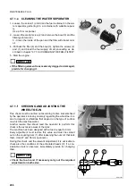
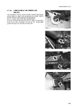
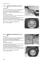
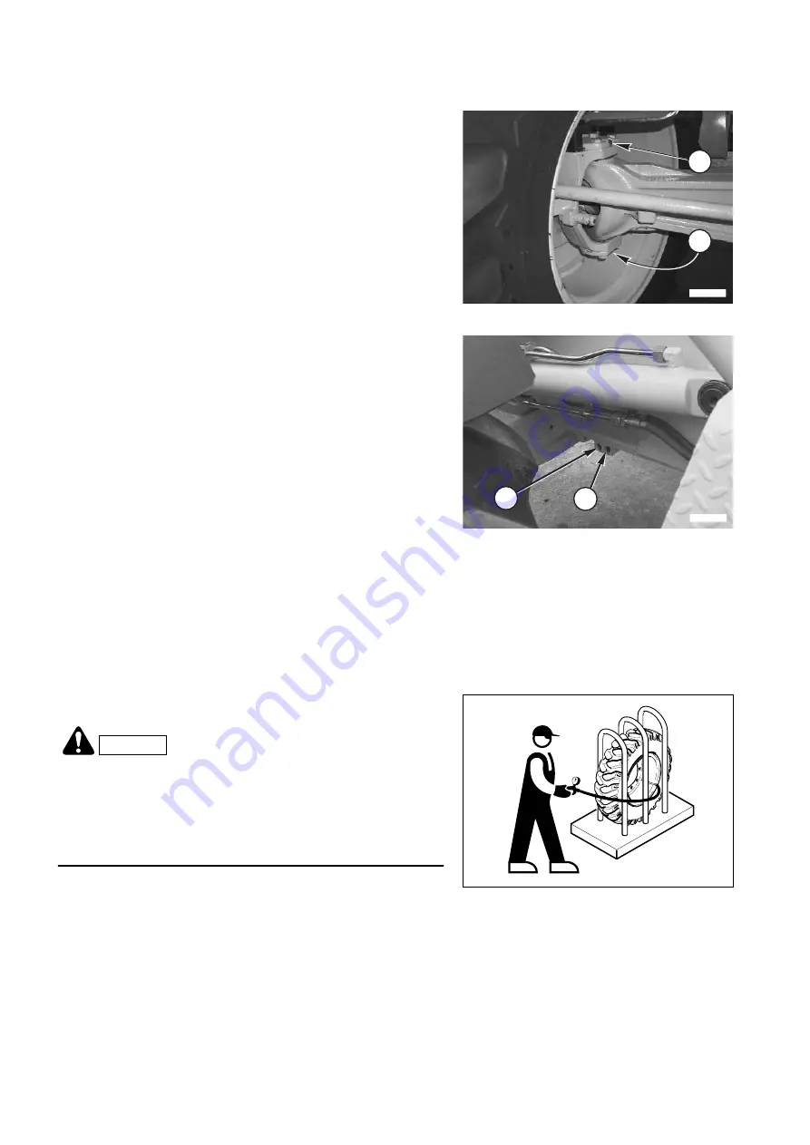
The lubrication points (1) of the wheel joints are indicated in the
figure and it is important to remember that they are located in
symmetrical positions, while the central joint is lubricated by
means of two grease nipples (2) positioned on the frame.
The lubrication must be carried out after carefully cleaning the
grease nipples, by applying the greasing pump supplied together
with the machine and using the prescribed grease.
(See “4.3 FUEL, COOLANT AND LUBRICANTS”).
Once the lubrication has been carried out, remove the contami-
nated grease that may have spread out of the joints and of the
central coupling.
RWAA9020
1
1
RWAA9030
2
2
DANGER
•
Inflate the tyres only after positioning them in a protection
cage.
•
To inflate the tyre, stand beside the external belt.
•
Do not exceed the pressures prescribed in chapter “5.1
TECHNICAL CHARACTERISTICS”.
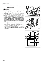
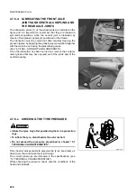
This check is indispensable to preserve the tyres, keep them ef-
ficient over time and make them last longer.
The correct pressures are indicated in the specifications, (see
“5.1 TECHNICAL CHARACTERISTICS”).
While checking the pressure, check also the conditions of the
tread and sidewalls.
RWA01680
Summary of Contents for 97SF11205
Page 2: ......
Page 12: ...10 THIS PAGE WAS INTENTIONALLY LEFT EMPTY ...
Page 21: ...SAFETY AND ACCIDENT PREVENTION ...
Page 56: ...54 THIS PAGE WAS INTENTIONALLY LEFT EMPTY ...
Page 57: ...THE MACHINE AND ITS OPERATIONS ...
Page 179: ...MAINTENANCE ...
Page 251: ...TECHNICAL SPECIFICATIONS ...
Page 257: ...AUTHORISED OPTIONAL EQUIPMENT ...

