114
INSTRUMENTS AND CONTROLS
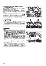
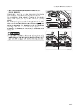
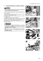
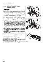
To use the backhoe control levers correctly, proceed as follows:
1 - With the machine at rest and the engine off, seat on the driv-
er’s seat and rotate it by 180° with respect to the driving posi-
tion.
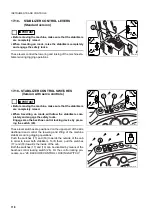
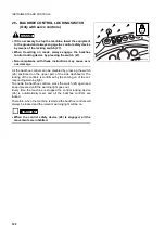
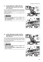
2 - Press the joystick locking levers (20-21) and lower both joy-
sticks (15-16) until reaching the desired operating position.
Once they have reached the desired position, release both
the locking levers (20-21) in order to lock the joysticks.?For
further information, see (20-21) JOYSTICK LOCKING LE-
VERS.
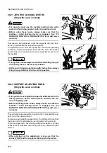
The position of the joysticks in operating conditions can be
adjusted by means of the relevant knobs (24-25) positioned
on the cab floor. For the correct adjustment procedure, keep
to the instructions given in paragraph (24-25) JOYSTICK
STROKE ADJUSTING KNOB.
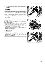
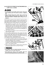
3 - Adjust the height of the supports (A) by means of the adjust-
ing knobs (22-23) , until finding the position that is most suita-
ble to your physical characteristics. For the correct
adjustment procedure, keep to the instructions given in para-
graph (22-23) SUPPORT ADJUSTING KNOB.
4 - Once the correct operating position of both joysticks has
been found, fasten the safety belt and start the machine by
proceeding as described in “3.6.2 STARTING THE ENGINE”.
Disengage the backhoe control locking device by pressing
the switch (26). The release of the controls is indicated by the
going out of the relevant warning light.
5 - At the end of work, if possible, lower the equipment to the
ground and engage the control locking device by pressing the
switch (26) again. The locking of the controls is confirmed by
the coming on of the relevant warning light.
6 - Before rotating the seat to the driving position, press the le-
vers (20-21) and at the same time raise the joysticks (15-16)
to bring them in vertical position.
Once the desired position has been reached, release the le-
vers (20-21) in order to lock the joysticks, respecting a given
safety distance from the rear window. If it is necessary to ad-
just the stroke of both joysticks, turn the adjusting screws po-
sitioned on the front part of the same according to the
procedure described in paragraph (24-25) JOYSTICK
STROKE ADJUSTING KNOB.
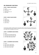
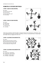
The control lever (15) is positioned on the operator’s left and
controls the arm and the swing, while the control lever (16) posi-
tioned on the operator’s right controls the boom and the bucket.
On request of the operator, the machine can be equipped with
two different control patterns at the same time, more precisely:
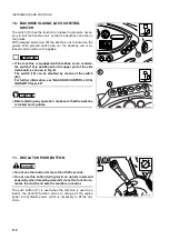
1 - ISO SYSTEM CONTROLS (Standard)
2 - KOMATSU SYSTEM CONTROLS (Optional)
The choice of the desired control pattern is up to the operator;
for the selection of the pattern desired, see paragraph (33) PAT-
TERN CHANGE CONTROL LEVER (on request).
The patterns illustrated below show the basic manoeuvres and
the combined manoeuvres that can be carried out with the two
systems.
15
20
22
24
RWA38340
A
RWA38350
21
23
25
A
16
Summary of Contents for 97SF11205
Page 2: ......
Page 12: ...10 THIS PAGE WAS INTENTIONALLY LEFT EMPTY ...
Page 21: ...SAFETY AND ACCIDENT PREVENTION ...
Page 56: ...54 THIS PAGE WAS INTENTIONALLY LEFT EMPTY ...
Page 57: ...THE MACHINE AND ITS OPERATIONS ...
Page 179: ...MAINTENANCE ...
Page 251: ...TECHNICAL SPECIFICATIONS ...
Page 257: ...AUTHORISED OPTIONAL EQUIPMENT ...

