


47
Chapter 3 Front-Panel Menu Operation
To Configure the Remote Interface
4
3
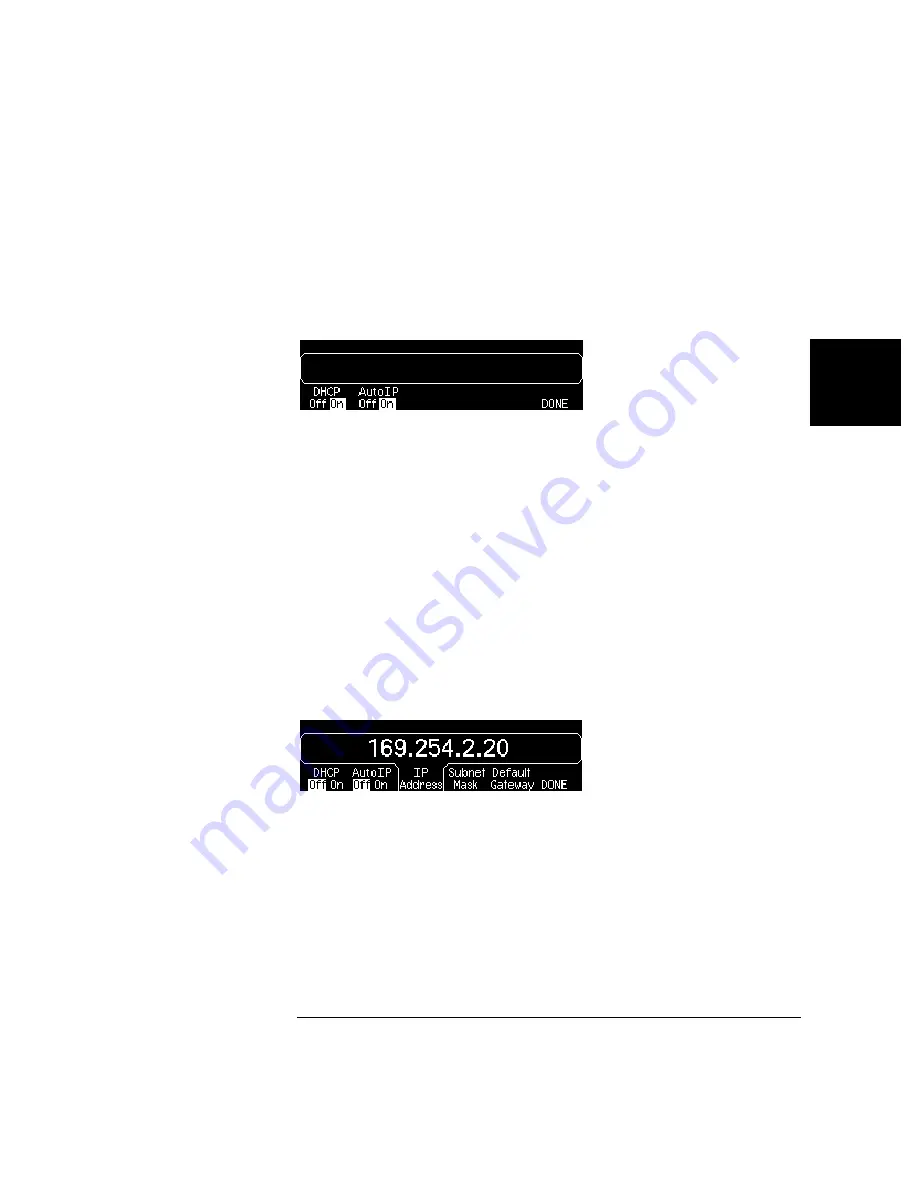
3 Establish an “IP Setup.”
To use the
Keysight
33210A on the network, you must first establish an
IP setup, including an IP address, and possibly a subnet mask and
gateway address. Press the
IP Setup
softkey. By default, both
DHCP
and
Auto IP
are set to
On
.
With
DHCP On
, an IP address will automatically be set by DHCP
(Dynamic Host Configuration Protocol) when you connect the
Keysight
33210A to the network, provided the DHCP server is found and is able to
do so. DHCP also automatically deals with the subnet mask and gateway
address, if required. This is typically the easiest way to establish LAN
communication for your instrument. All you need to do is leave
DHCP On
.
With
Auto IP On
, if DHCP fails to assign an IP address, Auto IP will
attempt to do so after a time-out period.
However, if you cannot establish communication by means of DHCP or
Auto IP, you will need to manually set an IP address, and a subnet mask
and gateway address if they are in use. Follow these steps:
a.
Set the “IP Address.”
Press the softkeys to select
DHCP Off
and
Auto IP Off
. The manual selection softkeys appear and the current IP
address is displayed:
Contact your network administrator for the IP address to use. All IP
addresses take the dot-notation form "nnn.nnn.nnn.nnn" where "nnn"
in each case is a byte value in the range 0 through 255. You can enter
a new IP address using the numeric keypad (not the knob). Just type
in the numbers and the period delimiters using the keypad. Use the
left cursor key as a backspace key. Do not enter leading zeros. For
further information, see “More about IP Addresses and Dot Notation”
at the end of this section.
Summary of Contents for 33210A
Page 1: ...Keysight 33210A 10 MHz Function Arbitrary Waveform Generator Service Guide ...
Page 2: ......
Page 3: ......
Page 10: ...8 ...
Page 13: ...1 1 Specifications ...
Page 19: ...2 2 Quick Start ...
Page 37: ...3 3 Front Panel Menu Operation ...
Page 52: ...50 3 ...
Page 53: ...4 4 Calibration Procedures ...
Page 96: ...94 Chapter 4 Calibration Procedures Calibration Errors 4 ...
Page 97: ...5 5 Block Diagram ...
Page 101: ...99 Chapter 5 Block Diagram Block Diagram 4 5 ...
Page 103: ...6 6 Disassembly and Repair ...
Page 128: ...126 Chapter 6 Disassembly and Repair Replaceable Parts 6 ...
Page 129: ...7 7 Backdating ...


