background image

46

Connection and setup

Always follow the operating instructions from your Pay-TV provider and the 
instructions supplied with the Smartcard and the CA (Conditional Access) module!

Smartcards and CI modules are not included with this product!

The cards and modules are issued by the respective Pay-TV providers, and contain the 
subscriber data and details of the channels for which the subscriber has paid. These channels 
are always scrambled.
Contact the Pay TV provider if you are interested in subscribing to a particular Pay TV channel.

You are responsible for the use of the Smartcard in the CI module!

The Smartcard sold by the Pay TV provider, specifi c to a particular encryption technology, is 
inserted into the CI module.

Store your card and PIN code securely when not in use!

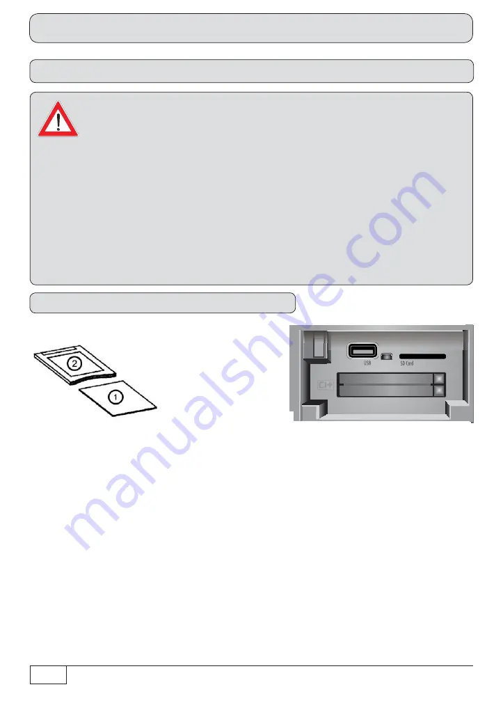
Common Interface (CI)/Smartcard reader

Inserting the CI module into the CI

The Common Interface (CI+) 

 of the UFS 924 is suitable for the use of two CI modules. It is located 

on the front of the receiver (under the  f ap). The CI module 

 accepts the Smartcard 

 (chip contacts 

pointing upwards and towards the socket board) and is then inserted in the CI+ insert position 

. The 

Smartcard  should be inserted into the CI module without exerting excessive force. 

The  same applies 

to inserting the CI module into the CI+ insert position.

Do not use excessive force and follow the instructions supplied with the Smartcard and the CI module. 

To remove the CI module press the corresponding ejection button 

 and pull it straight out backwards.

Inserting the Smartcard and the CI Module

Summary of Contents for UFS 924

Page 1: ...Network Internet access 44 Common Interface CI Smartcard reader 46 Inserting the Smartcard and the CI Module 46 Troubleshooting 47 Service 48 Technical Appendix 49 Advanced connection example 49 Tech...

Page 2: ...o high there is a risk of fire Moisture direct sunlight heat naked flames Protect the unit against moisture dripping and splashed water do not place any f lled objects such as vases on top of the unit...

Page 3: ...at base Repair Ensure that any repairs to your unit are carried out by qualif ed personnel Opening the unit and attempting to repair it yourself will void all warranty claims Improper work on the unit...

Page 4: ...anged or new data that are broadcast will be saved by the receiver As soon as the receiver is in the standby mode it can be disconnected from the mains at any time The information in these operating i...

Page 5: ...77 HDMI cable Power cable 2 batteries AAA 1 5 V Operating Instructions Part 1 2 and 3 Safety instructions multi lingual The accessories supplied may differ in appearance from those illustrated Loop th...

Page 6: ...6 Front rear view of the receiver front flap open Connection and setup 24 14 13 12 23 20 19 15 26 21 11 22 18 25 17 16 5 6 8 9 3 7 4 1 2 10...

Page 7: ...SPDIF Sony Philips Digital Interface Format for Dolby Digital AC 3 audio 21 Electrical digital data stream output SPDIF Sony Philips Digital Interface Format for Dolby Digital AC 3 audio 22 Video outp...

Page 8: ...eries supplied into the remote control Ensure correct polarity of the batteries the and markings are indicated inside the battery compartment Slide the cover back onto the housing until it locks in pl...

Page 9: ...the satellite reception system Use coaxial cable with an F standard connector see illustration on right HDMI Scart TV Conventional DiSEqC system Connect the satellite receiver HDMI or alternatively T...

Page 10: ...xample in the technical appendix SPDIF Sony Philips Digital Interface Format digital output for Dolby Digital AC 3 audio Connect the satellite receiver VCR AUX Scart socket to the video recorder DVR u...

Page 11: ...connected to a single cable system The receiver tuner inputs are factory preset in the installation menu to work with two separate Sat antenna connections In cases where only one antenna connection is...

Page 12: ...f rm the changed values setting call up the submenus Select change individual menu parameters navigation Cancel input go back First switch your TV set on and select the AV HDMI input you have used to...

Page 13: ...pe of screen display depending on your setting for the aspect ratio TV aspect ratio 4 3 Pan Scan or Letterbox TV aspect ratio 16 9 Always 16 9 or automatic HDMI YPbPr SCART or HDMI YPbPr Resolution He...

Page 14: ...ou can select the type of screen display mode for 4 3 broadcasts on a 16 9 TV set Either Normal Pillarbox Stretched full screen or Zoom in Pan Scan Audio Format via HDMI Here you can select the type o...

Page 15: ...ceiver in this section only one change selection is necessary in the rest of the first installation If you are not familiar with the details of your reception system note the following In many cases t...

Page 16: ...urrently selected setting is shown graphically in the connection example at the top left of the screen Either Separated The second tuner input of the receiver LNB2 IN receives its own signal input i e...

Page 17: ...vailable for Tuner 2 connection type Separated Tuner 2 signal configuration Same with Tuner 1 All settings are made on Tuner 1 The settings for the second tuner are automatically taken from the f rst...

Page 18: ...he desired satellite using the buttons Alternatively you can press the button to view a list of all stored satellites then select the required satellites from this list LNB Type If your reception syst...

Page 19: ...ne satellite four max for Tuner 1 you can now de f ne the settings as described above for the f rst satellite for the second satellite and then for the third and fourth satellites if selected When you...

Page 20: ...the button The following on screen display appears Press the green button Satellite Select the desired satellite using the buttons Alternatively you can press the button to view a list of all stored...

Page 21: ...your reception system Refer to the documentation for your reception system or seek assistance from a specialist engineer Off DiSEqC command is not repeated 1 DiSEqC command is repeated once 2 DiSEqC c...

Page 22: ...ou should now def ne the settings for the second tuner in the same way as you did for the f rst tuner Once you have completed the settings for both tuners and the satellites assigned to them the recei...

Page 23: ...urntable has only a restricted range in which it may turn before striking an obstruction such as a wall or tree Press the button The following on screen display appears The following buttons allow you...

Page 24: ...e borders You can now set new values for the limits Once you have set all the borders press the button Here select up to 64 satellites to be included in the signal on Tuner 1 Select the satellite you...

Page 25: ...ned LNB Frequencies MHz Enter the LNB frequencies Low High Limit using the number pad Now use the button to save the new values Test Transponder Select the T est Transponder f eld Here you can select...

Page 26: ...or the second satellite and for any other selected satellites When you have completed all settings for the selected satellites press the button When you have completed all settings for Tuner 1 press t...

Page 27: ...ld In this menu you can set the borders for your turntable This is particularly necessary if the turntable has only a restricted range in which it may turn before striking an obstruction such as a wal...

Page 28: ...ner 1 Go to the Select Satellites line Press the button The following on screen display appears example Here select up to 64 satellites to be included in the signal on Tuner 1 Select the satellite you...

Page 29: ...ther your settings are correct using the signal strength bar and signal quality bar If you have selected more than one satellite for Tuner 1 def ne the settings as just described for the f rst satelli...

Page 30: ...list LNB Type If your reception system does not have a universal LNB use the buttons to select the LNB types that are used in your reception system You can choose from the following LNB types Univers...

Page 31: ...Select the Test Transponder f eld Here you can select a transponder for checking whether your settings are correct using the signal strength bar and signal quality bar When you have completed all sett...

Page 32: ...fer to the documentation supplied with your system for the settings for the SCRs frequencies and any PIN assigned to the tuner Here you will find a printed list showing the assignment between the vari...

Page 33: ...r can then use this transmission frequency unless the PIN is input Select Yes You can now enter a PIN code 0 255 on the next line Tuner 1 PIN Code using the number pad Tuner 1 Select a free available...

Page 34: ...ing the buttons Alternatively you can press the button to view a list of all stored satellites then select the required satellites from this list LNB Type If your reception system does not have a univ...

Page 35: ...elected two satellites con f gure the settings as just described for the f rst satellite for the second satellite When you have completed all settings press the green button When you have completed al...

Page 36: ...atively you can press the button to view a list of all stored satellites then select the required satellites from this list Test Transponder Select the Test Transponder f eld Here you can select a tra...

Page 37: ...eiver can then use this transmission frequency unless the PIN is input Select Yes You can now enter a PIN code 0 255 on the next line T uner 1 PIN Code using the number pad Tuner 1 Select a free avail...

Page 38: ...ing the buttons Alternatively you can press the button to view a list of all stored satellites then select the required satellites from this list LNB Type If your reception system does not have a univ...

Page 39: ...signal strength bar and signal quality bar When you have completed all settings for the selected satellites press the button If you have selected two satellites con f gure the settings as just describ...

Page 40: ...Austria and Switzerland Channel search Connection and setup Satellite Now use the buttons to choose between the individual satellites you have set up or select the setting All Satellites If All Satel...

Page 41: ...the same way as the existing transponders When you have completed all settings press the green button The following displays appear at f rst example The receiver independently updates the ASTRA chann...

Page 42: ...nd time When you have completed the settings press the green button to complete the f rst installation After completing the search you will see the following on screen display example Press the button...

Page 43: ...te process refer to the section Mainmenu Service Menu Software Update by satellite in the Operating Instructions Part 2 Once the f rst installation has be successfully carried out you may change the c...

Page 44: ...n be made using the buttons or the numeric keypad An Internet connection is required for the use of the Red Bull MEDIA HOUSE PORTAL These settings should not be defined unless the receiver is linked i...

Page 45: ...nd press the button to conf rm Def ne the settings for your network as required When you have completed all the settings switch back to the Save f eld and press the button to conf rm Configuration exa...

Page 46: ...r encryption technology is inserted into the CI module Store your card and PIN code securely when not in use Common Interface CI Smartcard reader Inserting the CI module into the CI The Common Interfa...

Page 47: ...nt Check the batteries see also Inserting batteries into the remote control in the Operating Instructions Part 1 Receiver or remote control command set may have been unintentionally changed Set infrar...

Page 48: ...by HbbTV Select a channel transmitter that is provided by HbbTV e g ARD or ZDF Internet connection is not available Check that the cross over network cable is correctly connected clicked home receiver...

Page 49: ...49 Technical Appendix Advanced connection example HiFi system Network PC Laptop External hard drive Dolby digital system...

Page 50: ...e and change of picture content Approx 300 hours for SDTV approx 100 for HDTV depending on data rate and change of picture content Power supply Power supply voltage V Hz 230 50 60 Power consumption ma...

Page 51: ...51 Technical Appendix Sat IF connection examples Overvoltage protection KAZ 11 KAZ 12 Individual reception systems Community antenna network systems 4 x Sat IF Sat IF Sat IF Sat IF...

Page 52: ...52 Technical Appendix Overvoltage protection KAZ 11 KAZ 12 Community antenna systems 8 x Sat IF Multifeed Community antenna systems 16 x Sat IF Multifeed Sat IF Sat IF Sat IF Sat IF...

Page 53: ...53 Technical Appendix Overvoltage protection KAZ 11 KAZ 12 Single cable systems Sat IF...

Page 54: ...54 Technical Appendix Overvoltage protection KAZ 11 KAZ 12 Sat IF Sat IF...

Page 55: ...z B FRITZ Box TCP IP Adresse automatisch Funkstrecke Technical Appendix DHCP Receiver ON UFS 924 Internet Connection Examples for the Network Function Network cable Radio link PC Laptop TCP IP addres...

Page 56: ...PC Laptop Netzwerkkabel DHCP Server Router z B FRITZ Box TCP IP Adresse automatisch Funkstrecke DHCP Receiver ON UFS 924 Internet Network cable Radio link PC Laptop TCP IP address automatic DHCP serve...

Page 57: ...enthalten DHCP Server Router z B FRITZ Box Funkverbindung nur mit UFZ 130 m glich Funkstrecke TCP IP Adresse automatisch Internet Radio link PC Laptop TCP IP address automatic DHCP server router e g...

Page 58: ...92 168 0 13 TCP IP Adresse 192 168 0 12 TCP IP Adresse 192 168 0 11 TCP IP Adresse 192 168 0 10 Netzwerkkabel Netzwerkkabel Internet Network cable TCP IP address 192 168 0 13 DHCP server router e g FR...

Page 59: ...P IP Adresse 192 168 0 12 PC Laptop Netzwerkkabel Netzwerkkabel TCP IP Adresse 192 168 0 10 TCP IP Adresse 192 168 0 11 Internet TCP IP address 192 168 0 12 Switch HUB Network cable TCP IP address 192...

Page 60: ...Appendix DHCP Receiver OFF UFS 924 PC Laptop Gekreuztes Netzwerkkabel IP Adresse 192 168 0 10 IP Adresse 192 168 0 11 Switch HUB Cross over network cable IP address 192 168 0 10 IP address 192 168 0...

Page 61: ...61 For your notes For your notes...

Page 62: ...62 For your notes...

Page 63: ...63 For your notes...

Page 64: ...nternet www kathrein de KATHREIN Werke KG Anton Kathrein Stra e 1 3 P O Box 100 444 83004 Rosenheim GERMANY phone 49 8031 184 0 Fax 49 8031 184 385 936 4317 ZWT 1112 e Technical data subject to change...

Reviews: