


Tab. 1 Danger levels and their definitions (personal injury) ..................................................................
1
Tab. 2 Danger levels and their definition (damage to property) ............................................................
2
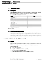
Tab. 3 Nameplate ..................................................................................................................................
4
Tab. 4 Extract from the options label .....................................................................................................
5
Tab. 5 Optional air treatment equipment ...............................................................................................
5
Tab. 6 Tool lubricator option ..................................................................................................................
5
Tab. 7 Compressed air distributor option ..............................................................................................
5
Tab. 8 Low temperature equipment options ..........................................................................................
5
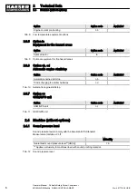
Tab. 9 Optional equipment for fire hazard areas ...................................................................................
6
Tab. 10 Automatic engine start/stop ........................................................................................................
6
Tab. 11 GSM/GPS unit ............................................................................................................................
6
Tab. 12 Sound pressure level .................................................................................................................
6
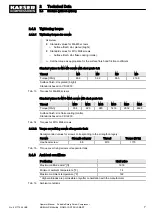
Tab. 13 Torques for M4–M8 screws ........................................................................................................
7
Tab. 14 Torques for M10–M24 screws ....................................................................................................
7
Tab. 15 Torque cover fixing screws oil separator tank ............................................................................
7
Tab. 16 Ambient conditions .....................................................................................................................
7
Tab. 17 Working pressure an volumetric flow (installation of the machine within the EU) ......................
8
Tab. 18 Working pressure an volumetric flow (installation of the machine outside of the EU) ................
8
Tab. 19 Compressed air distributor .........................................................................................................
8
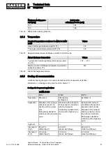
Tab. 20 Safety valve opening pressure ...................................................................................................
9
Tab. 21 Required temperatures readiness to switch to LOAD mode ......................................................
9
Tab. 22 Airend discharge temperature ....................................................................................................
9
Tab. 23 Cooling oil recommendations .....................................................................................................
9
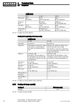
Tab. 24 Cooling oil recommendation (food processing) ..........................................................................
10
Tab. 25 Cooling oil charge quantity .........................................................................................................
10
Tab. 26 Kubota V 2403–CR Engine specifications ..................................................................................
11
Tab. 27 Engine specifications ..................................................................................................................
11
Tab. 28 Engine oil recommendation ........................................................................................................
12
Tab. 29 Initial engine oil quantity .............................................................................................................
12
Tab. 30 Water quality parameters for cooling water ................................................................................
13
Tab. 31 Initial filling of engine water cooler .............................................................................................
14
Tab. 32 Fluid volumes .............................................................................................................................
14
Tab. 33 Battery ........................................................................................................................................
15
Tab. 34 Road breaker lubricant recommendation ...................................................................................
15
Tab. 35 Interrelation between compressed air treatment and compressed air quality ............................
15
Tab. 36 Environmental conditions, low temperature equipment ..............................................................
15
Tab. 37 Power supply details ..................................................................................................................
16
Tab. 38 Technical data – Cooling water pre-heating device ....................................................................
16
Tab. 39 Battery charger specification ......................................................................................................
16
Tab. 40 GSM/GPS unit ............................................................................................................................
16
Tab. 41 Inspection intervals according to Ordinance on Industrial Health and Safety ............................
20
Tab. 42 Danger areas ..............................................................................................................................
26
Tab. 43 Safety signs ................................................................................................................................
27
Tab. 44 Safety signs ................................................................................................................................
29
Tab. 45 Instrument panel keys and displays ...........................................................................................
42
Tab. 46 Measures for re-commissioning the compressor after a long period of storage or de-
commissioning ............................................................................................................................
59
Tab. 47 Installation conditions checklist ..................................................................................................
59
Tab. 48 Measures required should the fuel tank be filled with the incorrect fuel type .............................
74
Tab. 49 Fuel / fuel specification ...............................................................................................................
76
Tab. 50 Plug sockets on the exterior of the machine ..............................................................................
80
Tab. 51 High-pressure washer setting .....................................................................................................
81
Tab. 52 Alarm messages and actions concerning the engine. ................................................................
86
Tab. 53 Alarm messages and actions concerning the compressor unit ..................................................
88
List of Tables
No.: 901779 08 USE
Operator Manual Portable Rotary Screw Compressor
MOBILAIR M58utility SIGMA CONTROL SMART
ix


