Chapter 5---Electronics
5-6
Model 250 Service Manual
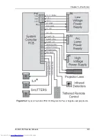
Figure 5-5
System Controller PCB I/O Diagram for other PCBs.
System Controller PCB - Inputs
/LV_OK - signal from the Low Voltage Power Supply; it tells the System
Controller PCB that all the non-standby supply voltages are working.
/HV_OK - signal from the High Voltage Power Supply; it tells the System
Controller PCB that all the high voltage supplies are working.
/LAMP_OK - signal from the Arc Lamp Power Supply.
/LAMP_LIT - signal from the Arc Lamp Power Supply; it tells the System
Controller PCB that the Arc Lamp is lit.
ODD_FIELD - Square wave signal from the Raster Timing Generator PCB, with
50% duty cycle that is low during odd fields of an Interlace signal. This signal is
high during noninterlaced signals.
Summary of Contents for 250
Page 16: ...Chapter 2 System Description Model 250 Service Manual 2 9 ...
Page 43: ...Chapter 4 Optical 4 10 Model 250 Service Manual Figure 4 6 Optical Path ...
Page 55: ...Chapter 5 Optical 3 4 22 Model 100 Service Manual ...
Page 91: ...Chapter 5 Electronics 5 36 Model 250 Service Manual Figure 5 22 Scan Reversal PCB I O Diagram ...
Page 131: ...Chapter 5 Electronics 5 76 Model 250 Service Manual Figure 5 44 Backplane Diagram right side ...
Page 132: ...Chapter 5 Electronics Model 250 Service Manual 5 77 ...
Page 138: ...Chapter 6 Miscellaneous Items 6 6 Model 250 Service Manual ...
Page 167: ...Chapter 7 Troubleshooting Model 250 Service Manual 7 29 ...
Page 181: ...Chapter 8 Software and Protocol 8 14 Model 250 Service Manual ...
Page 185: ...Chapter 9 Parts List 9 4 Model 250 Service Manual ...

