
Chapter 7---Troubleshooting
Model 250 Service Manual
7-11
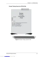
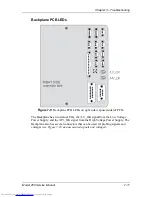
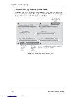
Backplane PCB LEDs
Figure 7-9
Backplane PCB LEDs on right side (exposed side)of PCB
.
The Backplane has two status LEDs, the /LV_OK signal from the Low Voltage
Power Supply, and the /HV_OK signal from the High Voltage Power Supply. The
Backplane also has several connectors that can be used for probing signals and
voltages (see Figure 7-18 and associated signals and voltages).
Summary of Contents for 250
Page 16: ...Chapter 2 System Description Model 250 Service Manual 2 9 ...
Page 43: ...Chapter 4 Optical 4 10 Model 250 Service Manual Figure 4 6 Optical Path ...
Page 55: ...Chapter 5 Optical 3 4 22 Model 100 Service Manual ...
Page 91: ...Chapter 5 Electronics 5 36 Model 250 Service Manual Figure 5 22 Scan Reversal PCB I O Diagram ...
Page 131: ...Chapter 5 Electronics 5 76 Model 250 Service Manual Figure 5 44 Backplane Diagram right side ...
Page 132: ...Chapter 5 Electronics Model 250 Service Manual 5 77 ...
Page 138: ...Chapter 6 Miscellaneous Items 6 6 Model 250 Service Manual ...
Page 167: ...Chapter 7 Troubleshooting Model 250 Service Manual 7 29 ...
Page 181: ...Chapter 8 Software and Protocol 8 14 Model 250 Service Manual ...
Page 185: ...Chapter 9 Parts List 9 4 Model 250 Service Manual ...

















![NEC MT800[1].PART1 User Manual preview](http://thumbs.mh-extra.com/thumbs/nec/mt800-1-part1/mt800-1-part1_user-manual_250403-1.webp)


