Chapter 2---System Description
Model 250 Service Manual
2-3
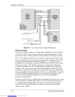
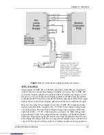
Igniter Assembly
The Igniter Assembly provides the high voltage pulse that lights the Arc Lamp
and acts as a link from the Arc Lamp Power Supply to the Arc Lamp after the Arc
Lamp has been lit.
!
Igniter - The Igniter actually performs three functions. It is a step-up
transformer that supplies the high voltage pulse to light the Arc Lamp. It
also supplies the spark gap for the high voltage pulse. Once the Arc Lamp
is lit, the Igniter acts as a link between the Arc Lamp Power Supply and
the Arc Lamp for steady state operation.
!
Laser Power Supply - The Laser Power Supply provides the voltage for
the spark gap. The spark gap produces a high voltage pulse in the Igniter
that lights the Arc Lamp.
2.3
Optical Section
The optical section of the Model 250 consists of the Arc Lamp Module, the
Optical Path, the ILA
®
, the CRTs, the Relay Lenses and the Projection Lens.
Arc Lamp Module
The Arc Lamp Module supplies high intensity light for the Model 250. Its output
is rated at 2 kW. The Arc Lamp has an expected 50% lifetime (half of initial light
output) of 1000 hours.
Optical Path
The Optical Path consists of all the optical components that transmit, filter,
separate, bend, or straighten the Arc Lamp light. The Optical Path also includes
Polarizing Prisms, Prepolarizing Prisms, Steering Prisms and the 4P Combining
Prism that control the image path inside the Prism Assembly.
!
Cold Mirrors (3) - The Cold Mirrors remove infrared light rays, which
contain most of the heat, from the white light coming from the Arc Lamp.
There are three Cold Mirrors, the first one is located in front of the Arc
Lamp, and the other two are located after the Light Pipe.
CAUTION!
The term "cold mirror" is used because
the mirror passes infrared light and its reflection contains only "cold'
light that does not transmit appreciable heat. As a result of the
absorption of infrared heat radiation, "cold" mirrors get very hot.
!
Light Pipe - The Light Pipe acts as an Integrator to spread out the beam of
light creating a uniform distribution of light across the face of the ILA
®
.
This will result in a more uniform image on the screen
Summary of Contents for 250
Page 16: ...Chapter 2 System Description Model 250 Service Manual 2 9 ...
Page 43: ...Chapter 4 Optical 4 10 Model 250 Service Manual Figure 4 6 Optical Path ...
Page 55: ...Chapter 5 Optical 3 4 22 Model 100 Service Manual ...
Page 91: ...Chapter 5 Electronics 5 36 Model 250 Service Manual Figure 5 22 Scan Reversal PCB I O Diagram ...
Page 131: ...Chapter 5 Electronics 5 76 Model 250 Service Manual Figure 5 44 Backplane Diagram right side ...
Page 132: ...Chapter 5 Electronics Model 250 Service Manual 5 77 ...
Page 138: ...Chapter 6 Miscellaneous Items 6 6 Model 250 Service Manual ...
Page 167: ...Chapter 7 Troubleshooting Model 250 Service Manual 7 29 ...
Page 181: ...Chapter 8 Software and Protocol 8 14 Model 250 Service Manual ...
Page 185: ...Chapter 9 Parts List 9 4 Model 250 Service Manual ...


