Chapter 5---Electronics
5-8
Model 250 Service Manual
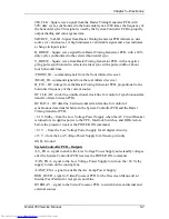
RGB_THRES - red, green, or blue Threshold correction information to the Video
Processor PCB.
RGB_SENS - red, green, or blue Sensitivity correction information to the Video
Processor PCB.
ISYNC - 5 MHz clock to the Raster Timing Generator PCB, used to generate the
internal sync signals
Y_RGB_CONV - control signals to Convergence Deflection PCB for Red, Green,
or Blue Convergence in the y-axis (full-scale correction is about 1 Vpp).
X_RGB_CONV - control signals to Convergence Deflection PCB for Red, Green,
or Blue Convergence in the x-axis (full-scale correction is about 1 Vpp).
CORR_SYNC - Square wave HCT level synchronous signal to the Convergence
Deflection PCB for the horizontal axis.
RGB_SHUT - Signal to operate the red, green, and blue shutters.
LENS_ZOOM - Signal to the zoom motor of the Projection Lens.
LENS_FOCUS - Signal to the focus motor of the Projector Lens.
System Controller PCB - Operation
Startup Functions
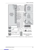
When AC Circuit Breaker is powered ON, the Low Voltage Power Supply sends
+5.1 V stdby voltage to the System Controller PCB. The +5.1 V Stdby powers the
CPU and IR Detector so the System Controller PCB can receive and respond to
the POWER ON command. The System Controller PCB sends a /FAN_ENA
signal back to the LVPS turning on the +24 V Stdby to turn the cooling fans on.
When the System Controller PCB receives a POWER ON command from either
the IR remote control or a PC, it sends the /LV_ENA signal to the Low Voltage
Power Supply. This turns on all the non-standby (±15 V, +5.1 V, +6.2 V, +24 V,
+80 V) voltages. After all the non-standby voltages power up, the LVPS sends the
/LV_OK signal back to the System Controller PCB to tell it that all the non-
standby voltages are present.
When the System Controller PCB receives a POWER ON command, it receives
the /LAMP_OK signal from the Arc Lamp Power Supply and sends the
/LAMP_ENA signal back to the Arc Lamp Power Supply to turn it on. The Arc
Lamp lights, and the Arc Lamp Power Supply sends a /LAMP_LIT signal back to
the System Controller PCB (see Figure 5-6).
The System Controller PCB also monitors the status of the High Voltage Power
Supply through the /HV_OK signal.
Summary of Contents for 250
Page 16: ...Chapter 2 System Description Model 250 Service Manual 2 9 ...
Page 43: ...Chapter 4 Optical 4 10 Model 250 Service Manual Figure 4 6 Optical Path ...
Page 55: ...Chapter 5 Optical 3 4 22 Model 100 Service Manual ...
Page 91: ...Chapter 5 Electronics 5 36 Model 250 Service Manual Figure 5 22 Scan Reversal PCB I O Diagram ...
Page 131: ...Chapter 5 Electronics 5 76 Model 250 Service Manual Figure 5 44 Backplane Diagram right side ...
Page 132: ...Chapter 5 Electronics Model 250 Service Manual 5 77 ...
Page 138: ...Chapter 6 Miscellaneous Items 6 6 Model 250 Service Manual ...
Page 167: ...Chapter 7 Troubleshooting Model 250 Service Manual 7 29 ...
Page 181: ...Chapter 8 Software and Protocol 8 14 Model 250 Service Manual ...
Page 185: ...Chapter 9 Parts List 9 4 Model 250 Service Manual ...

