Chapter 4---Optical
4-2
Model 250 Service Manual
4.1 Arc
Lamp
The Arc Lamp is the beginning of the high intensity Light Path. It is located
inside a housing on the right side of the Optical Support Assembly (see Figure
4-5).
Arc Lamp - Main Functions:
The Arc Lamp is a single component composed of a Xenon gas bulb at the center
of a compound elliptical reflector. It supplies the high intensity white light used
by the projector to put a very bright image on the screen. The expected 50% life
(half of initial light output) of an Arc Lamp is approximately 1000 hours.
Arc Lamp - Inputs
!
32 kV pulse to light the Arc Lamp Power Supply
!
2 kW constant power during normal operation
Arc Lamp - Operation
The Arc Lamp Power Supply and the Igniter Assembly work together to produce
a 32 kV pulse that ignites the Arc Lamp. After the Arc Lamp lights, the voltage
from the Arc Lamp Power Supply drops to a constant 25-31 volts at 70-85 amps.
It will stay at this level during normal Arc Lamp operation.
Arc Lamp - Service Adjustments
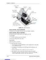
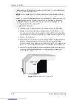
When a new Arc Lamp is installed, it will need to be aligned using the Arc Lamp
adjustment fixture located inside the Arc Lamp housing (see Figure 4-2).
Arc Lamp Adjustment
Tools Needed
Large Flatblade screwdriver
4-mm Hex-head wrench
Equipment Needed
Minolta Illumination Meter T-1 or equivalent
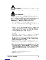
To align the Arc Lamp:
1.
Remove the front cover (see Section 6.1).
2.
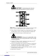
Loosen the spider lock down bolt (see Figure 4-4).
3.
Power the projector ON and let it run for 15 minutes to stabilize.
4.
Verify that the "Shutters on Hide" box is checked in the System-
Preferences menu, then use the RGB key and the HIDE key to hide Red
and Blue. This prevents light coming from the Red and Blue ILA
®
s.
5.
Open the fan door of the Arc Lamp Enclosure housing using the large
Flatblade screwdriver to rotate the retaining screws 90
°
This gains access
to the three Arc Lamp alignment screws. The Arc Lamp fan disconnects
when this door is opened.
Summary of Contents for 250
Page 16: ...Chapter 2 System Description Model 250 Service Manual 2 9 ...
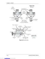
Page 43: ...Chapter 4 Optical 4 10 Model 250 Service Manual Figure 4 6 Optical Path ...
Page 55: ...Chapter 5 Optical 3 4 22 Model 100 Service Manual ...
Page 91: ...Chapter 5 Electronics 5 36 Model 250 Service Manual Figure 5 22 Scan Reversal PCB I O Diagram ...
Page 131: ...Chapter 5 Electronics 5 76 Model 250 Service Manual Figure 5 44 Backplane Diagram right side ...
Page 132: ...Chapter 5 Electronics Model 250 Service Manual 5 77 ...
Page 138: ...Chapter 6 Miscellaneous Items 6 6 Model 250 Service Manual ...
Page 167: ...Chapter 7 Troubleshooting Model 250 Service Manual 7 29 ...
Page 181: ...Chapter 8 Software and Protocol 8 14 Model 250 Service Manual ...
Page 185: ...Chapter 9 Parts List 9 4 Model 250 Service Manual ...


