Chapter 5---Electronics
Model 250 Service Manual
5-3
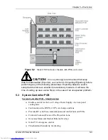
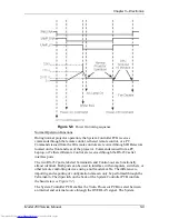
Figure 5-2
Model 250 Electronics Module with PCBs (side view).
CAUTION
!
It is very strongly recommended that setup
data be downloaded (Exported, see section 8.2 Importing/Exporting) before
performing any of the following procedures. Exporting baseline source
setup data to disk is an excellent precautionary measure. It will save the
time of setting up new source file(s) in the case of an unexpected problem
.
5.3 System
Controller
PCB
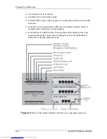
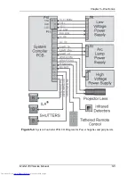
System Controller PCB - Main Function
!
Enables control for the Low Voltage Power Supply, Arc Lamp and
cooling fans.
!
Fault monitors the HVPS, LVPS, Arc Lamp, and fans.
!
Provides IIC serial bus communication and control between PCBs.
!
Controls Zoom and Focus of the Projection Lens.
!
Generates Menu and Internal Patterns Overlays
!
X and Y Convergence control
!
Threshold and Sensitivity for shading
Summary of Contents for 250
Page 16: ...Chapter 2 System Description Model 250 Service Manual 2 9 ...
Page 43: ...Chapter 4 Optical 4 10 Model 250 Service Manual Figure 4 6 Optical Path ...
Page 55: ...Chapter 5 Optical 3 4 22 Model 100 Service Manual ...
Page 91: ...Chapter 5 Electronics 5 36 Model 250 Service Manual Figure 5 22 Scan Reversal PCB I O Diagram ...
Page 131: ...Chapter 5 Electronics 5 76 Model 250 Service Manual Figure 5 44 Backplane Diagram right side ...
Page 132: ...Chapter 5 Electronics Model 250 Service Manual 5 77 ...
Page 138: ...Chapter 6 Miscellaneous Items 6 6 Model 250 Service Manual ...
Page 167: ...Chapter 7 Troubleshooting Model 250 Service Manual 7 29 ...
Page 181: ...Chapter 8 Software and Protocol 8 14 Model 250 Service Manual ...
Page 185: ...Chapter 9 Parts List 9 4 Model 250 Service Manual ...

