2-71
johNSoN coNtroLS
ForM 102.20-N1 (1109)
2
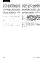
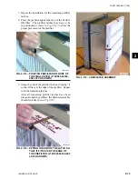
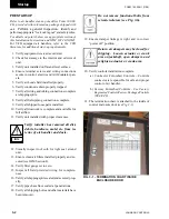
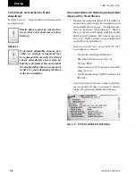
4. Repeat the latch installation with the remaining
latches.
Note the orientation of the latch to the
knockouts in Fig.2-107.
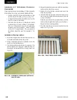
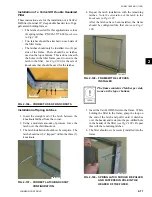
After the latches have been installed, the frame
should be configured like that
shown in Fig.2-
108.
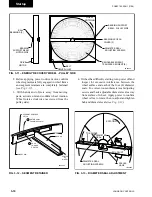
Fig. 2-108 – FRAME With 4 lAtChES
inStAllEd.
The frame contains 2 latches per side,
none on the top or bottom.
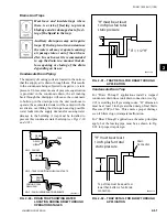
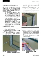
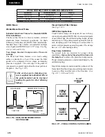
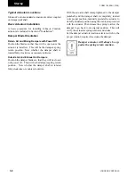
5 Insert the VariCel DH filter into the frame. While
holding the filter in the frame, grasp the loop on
the end of the latch and pull it until it stretches
over the header and rests into the pre-drilled hole
in the header of the filter
(see Fig.2-109).
Repeat
this with the remaining latches.
6. The filter should now be securely installed into the
frame
.
Fig. 2-109 – SPRing lAtCh ShOuld BE PullEd
And FAStEnEd in hOlE in thE
hEAdER OF thE FiltER.
LD010183
LD010184
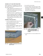
Installation of a Varicel DH Double Headered
Filter
These instructions are for the installation of a VariCel
DH filter (nominal 12” deep double header) into 16 ga.
galvanized holding frames.
• The latches needed for this application are four
(4) spring latches, P/N 026-35778-006
(as shown
in Fig.2-98.
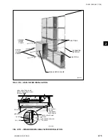
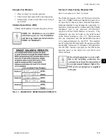
• Two latches should be attached on each side of
the filter frame.
• The latches should only be installed, two (2) per
side of the frame. There should be no latches
used on the top or bottom. This is done to match
the holes in the filter frame, used to secure the
latch to the filter.
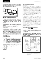
See Fig.2-106
for the sets of
knockouts that should be used for the latches.
Fig. 2-106 – CORRECt uSE OF KnOCKOutS
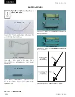
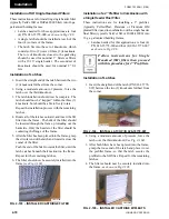
installation of Spring latches
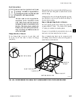
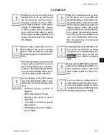
1. Insert the straight end of the latch between the
knockouts furthest from the corner.
2. Using a moderate amount of pressure, force the
latch over the third knockout
.
3. The latch installation should now be complete. The
latch should now be “trapped” within the three (3)
knockouts
.
Fig. 2-107 – CORRECt lAtCh/KnOCKOut
COnFiguRAtiOn.
DO NOT USE
LD010150
LD010154
Summary of Contents for YORK SOLUTION LD09624
Page 4: ...johnson controls 4 FORM 102 20 N1 1109 THIS PAGE INTENTIONALLY LEFT BLANK ...
Page 10: ...johnson controls 10 FORM 102 20 N1 1109 THIS PAGE INTENTIONALLY LEFT BLANK ...
Page 16: ...johnson controls 16 FORM 102 20 N1 1109 THIS PAGE INTENTIONALLY LEFT BLANK ...
Page 30: ...johnson controls 1 8 FORM 102 20 N1 1109 THIS PAGE INTENTIONALLY LEFT BLANK ...
Page 106: ...johnson controls 2 76 FORM 102 20 N1 1109 THIS PAGE INTENTIONALLY LEFT BLANK ...


