3-5
johnson controls
ForM 102.20-n1 (1109)
3
Check Operation of Dampers
Ensure unit will not operate with all dampers closed.
Linkage design and/or damper linkage may not be
provided by Johnson Controls. Airflow control
dampers may be operated with pneumatic or electric
actuator/controllers.
Prior to occupancy, test ventilation sys-
tem to ensure that outdoor air dampers
operate properly in accordance with
the system design.
Airflow Control Dampers
Many combinations of damper sizes are available to
control the flow, the mixing of return air and outside
air in the air inlet section of the unit may be supplied
as follows:
• One hundred percent outside air, 100% return
air.
• One hundred percent outside air, 0% return air.
• Zero percent outside air, 100% return air.
• Economizer Section - 100% outside air, 100%
return air, 100% exhaust air or mixed air.
On dampers with actuators, intercon-
necting damper linkage is only pro-
vided when selected by Sales.
Dampers, actuators, controls and link-
age must be checked prior to applying
power to the operators making sure
nothing will obstruct the operation of
the dampers. Do not overdrive damper
actuators as this may cause damage to
the dampers.
Return air dampers may be closed for
shipping. Loosen actuator or crank
arm on jackshaft, open dampers, and
retighten actuator or crank arm. Field
is responsible for adjustments.
IAQ
START-UP
Temporary Operation: This equip-
ment should not be operated until after
complete Start-up as outlined in this
guide. Do not allow the unit to run
on temporary power that is not reliable
and could be off/on periodically or
rapidly. Also, protect it from irregular
voltages and surges.
We strongly recommend the startup
technician use the checklist provided
and record the gathered information
in the appropriate fields. If there are
any specific questions refer to the
document list on the checklist. Also,
at the end of Section 3 is located a list
of references for various check points
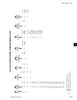
on the checklist (Inspection Require
-
ments). This is a guide to "How To"
information in this and other docu-
ments.
Filter media must be installed prior
to Start-up. Use media provided or
temporary media that will adequately
protect the components in the air
stream and duct system.
Check Operation of Fans
1. Energize power to the unit disconnect switch.
2. Verify correct voltage, phase and cycles.
3. Energize fan motor(s), briefly (bump) and check
for correct fan rotation.
If rotation is incorrect:
1. On three-phase equipment reverse any 2 motor
leads at the load side of last starter component.
2. On single-phase equipment, follow wiring dia-
gram on motor housing or inside motor terminal
box.
3. Re-check for correct fan rotation.
Summary of Contents for YORK SOLUTION LD09624
Page 4: ...johnson controls 4 FORM 102 20 N1 1109 THIS PAGE INTENTIONALLY LEFT BLANK ...
Page 10: ...johnson controls 10 FORM 102 20 N1 1109 THIS PAGE INTENTIONALLY LEFT BLANK ...
Page 16: ...johnson controls 16 FORM 102 20 N1 1109 THIS PAGE INTENTIONALLY LEFT BLANK ...
Page 30: ...johnson controls 1 8 FORM 102 20 N1 1109 THIS PAGE INTENTIONALLY LEFT BLANK ...
Page 106: ...johnson controls 2 76 FORM 102 20 N1 1109 THIS PAGE INTENTIONALLY LEFT BLANK ...


