2-33
johNSoN coNtroLS
ForM 102.20-N1 (1109)
2
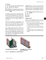
d) Attach the cover angle to the air handler and
pipe chase panels. Install self drilling screws
removed earlier to top and bottom holes on
cover angle.
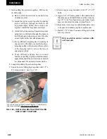
e) Starting at the top and alternating between
the air handler and pipe chase, continue
installing self drilling screws until reaching
the bottom. Use caution not to strip the
housing
(see Fig.2-50).
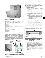
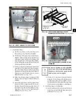
6. Install the Pipe Chase Baserail Covers
(See Fig. 2-51)
a) On the perimeter of the cover, caulk the
underside as shown.
b) Apply cover to exposed baserail seam
between pipe chase and air handler (both
sides) (no screws required).
All pipe chase floor penetrations must
be flashed, sealed and insulated to
prevent condensation entering build-
ing.
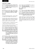
Fig. 2-51 – BASERAil COVER APPliCAtiOn
LD12032B
PIPECHASE BASERAIL
COVER
APPLY CAULK AROUND
PERIMETER OF PART
BEFORE APPLYING TO
BASERAIL SEAM.
Caulk
Application
Cover
Installation
1) CAULK PERIMETER
OF COVER AS SHOWN
BELOW.
2) APPLY COVER TO
BASERAIL SEAM.
PIPECHASE BASERAIL
UNIT
BASERAIL
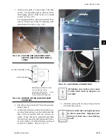
Put notch on cover angle
on Air Handler side.
Put notch on cover angle
on Air Handler side.
AIR HANDLER
AIR HANDLER
PIPE CHASE
PIPE CHASE
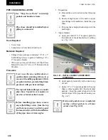
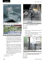
Fig. 2-49 – PROPER POSitiOning OF COVER
AnglE With nOtCh On AiR
hAndlER SidE
LD12563
Alternating between Air
Handler and Pipe Chase,
install remaining self-drilling
screws starting at the top and
working toward the bottom.
Alternating between Air
Handler and Pipe Chase,
install remaining self-drilling
screws starting at the top and
working toward the bottom.
Install (2) top and (2) bottom
self-drilling screws first.
Install (2) top and (2) bottom
self-drilling screws first.
AIR HANDLER
AIR HANDLER
PIPE CHASE
PIPE CHASE
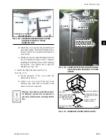
Fig. 2-50 – PROPER PAttERn FOR inStAlling
SElF-dRilling SCREWS tO COVER
AnglE
LD12562
Summary of Contents for YORK SOLUTION LD09624
Page 4: ...johnson controls 4 FORM 102 20 N1 1109 THIS PAGE INTENTIONALLY LEFT BLANK ...
Page 10: ...johnson controls 10 FORM 102 20 N1 1109 THIS PAGE INTENTIONALLY LEFT BLANK ...
Page 16: ...johnson controls 16 FORM 102 20 N1 1109 THIS PAGE INTENTIONALLY LEFT BLANK ...
Page 30: ...johnson controls 1 8 FORM 102 20 N1 1109 THIS PAGE INTENTIONALLY LEFT BLANK ...
Page 106: ...johnson controls 2 76 FORM 102 20 N1 1109 THIS PAGE INTENTIONALLY LEFT BLANK ...

