2-3
johNSoN coNtroLS
ForM 102.20-N1 (1109)
2
Curb Assembly and installation instructions
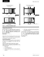
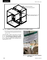
See Fig. 2-2
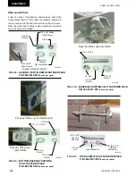
1. Unpack shipping package, layout pieces and
parts according to the exploded views and check
against Bill of Materials.
2. Layout all channel pieces as shown. Make certain
that all channel tabs are located on inside of mat-
ing channel
Make certain that all curb walls ac-
cessories and flanges, which may
have been distorted in handling, are
straightened before assembly.
3. Attach curb walls together to form rectangular
perimeter as shown, leaving bolts loose.
After the curb is set in place, ensure
proper consideration has been given
to the air duct openings through the
roof.
4. The curb installation drawing (see Fig. 2-2)
shows a gasket that is mounted between the curb
and the unit. This gasket is shipped with the curb
parts. Install the curb gasket before setting the
unit on the curb. The gasket forms an air seal
between the unit and the curb and serves as a
dampener, preventing metal-to-metal contact
between the unit and curb. However, the gasket
should not be used as a vibration isolator where
the prevention of noise and vibration transmis-
sion into the building is critical.
When unit is shipped in sections, the
curb gasket is to be replaced with caulk
provided by contractor.
5. After verifying curb is square and level, tighten
all bolts and then anchor as appropriate.
If bolts are tightened after anchoring,
curb will be pulled, twisted and torqued
out of square.
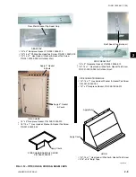
6. Pipe Chase Curb Assembly - once curb is square
and level mark the exact location for the pipe
chase curb. Drill and assemble.
Pipe Chase Curb location:
Unit submittal drawing package has
a Johnson Controls curb drawing
showing dimensions of curb and pipe
chase.
7. The curb should be insulated and roofed as re-
quired. Refer to SMACNA for counter flash.
Steel Frame
When a steel frame is used to support the unit, it must
be level, flat without uneven steel frame joints, and
support the unit around the full perimeter. As a general
rule, cross members should be placed every 96" in
addition to every shipping split.
indoor units (Site Prep)
Concrete pads often are not as flat
as they should be. Shimming and/or
grouting may be necessary. This is to
ensure the unit base is on a perfectly
flat plane.
Summary of Contents for YORK SOLUTION LD09624
Page 4: ...johnson controls 4 FORM 102 20 N1 1109 THIS PAGE INTENTIONALLY LEFT BLANK ...
Page 10: ...johnson controls 10 FORM 102 20 N1 1109 THIS PAGE INTENTIONALLY LEFT BLANK ...
Page 16: ...johnson controls 16 FORM 102 20 N1 1109 THIS PAGE INTENTIONALLY LEFT BLANK ...
Page 30: ...johnson controls 1 8 FORM 102 20 N1 1109 THIS PAGE INTENTIONALLY LEFT BLANK ...
Page 106: ...johnson controls 2 76 FORM 102 20 N1 1109 THIS PAGE INTENTIONALLY LEFT BLANK ...


