


johNSoN coNtroLS
2-58
ForM 102.20-N1 (1109)
installation
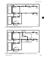
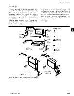
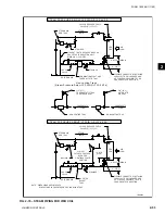
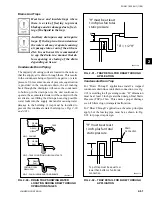
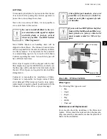
When the condensing unit has three compressors
per circuit, two coil circuits should be used for each
refrigerant circuit (Fig. 2-87). Each coil circuit must
have a dedicated TXV and distributor to handle one coil
circuit and the LLSV should be sized to handle the full
capacity of the refrigerant circuit. The hot gas bypass
line should be connected to all of the distributors in the
coil circuit.
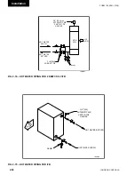
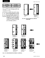
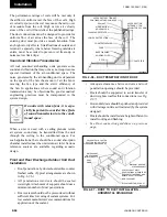
In the case of a stacked coil with four coil circuits piped
to a condenser with six compressors, the coil circuits
would be face-split and interlaced with two interlaced
circuits on the lower coil section and two on the upper
(Fig. 2-89).
Fig. 2-84 – OnE COil CiRCuit PER
REFRigERAnt CiRCuit
100% Capacity
dx Coil
condensing Unit
LD09148
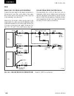
Fig. 2-85 – tWO COil CiRCuitS PER
REFRigERAnt CiRCuit
dx Coil
condensing Unit
compressor #1
compressor #2
txv
LLSv
txv
LD09149
dx Coil
condensing Unit
compressor #1
compressor #2
txv
LLSv
LLSv
txv
LD09150
Fig. 2-86 – dO nOt uSE thE ABOVE
COnFiguRAtiOn.
Fig. 2-87 – thREE COMPRESSOR YCul
LD09151
DX Coil
Condensing Unit
Compressor #1
Compressor #3
Feeds both Circuits
Compressor #2
TXV
LLSV
TXV
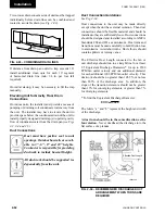
dx Coil
condensing Unit
compressor #1
compressor #3
Feeds both Circuits
compressor #2
txv
LLSv
LLSv
txv
LD09152
Fig. 2-88 – dO nOt uSE thE ABOVE
COnFiguRAtiOn.
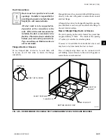
When sizing TXV's, each TXV must
be sized for the refrigerant circuit
tonnage divided by the number of
DX coil liquid distributors. The TXV
should be equal to or smaller than the
calculated value.
The first three compressors (
see Fig. 2-89
) would
be tied into LLSV1, TXV1 and TXV2. This would
provide full-face control of the coil at even the lowest
cooling loads. Both distributors on each of the coil
circuits would include auxiliary side connectors for
HGBP.
The second set of 3 compressors would be tied into
LLSV2, TXV3 and TXV4 to maintain full-face control
at higher loads.
Reference Form 050.40-ES3 Section 9
for compressor staging solutions.
The more control stages used, the more precise
the control of the air temperature will be. Smaller
incremental changes in capacity will result in a more
consistent DX coil leaving air temperature. This will
eliminate temperature swings in the conditioned space
and improve the comfort level, but more importantly, a
consistent space temperature is crucial to many process
applications. The smaller changes in capacity that
result from using a greater number of control stages
will also extend equipment life. The most important
thing to remember is to maintain full-face control of
the coil at all cooling loads. When row split coils are
used, make sure that the first LLSV is energized with
the last coil circuit in the leaving air stream. This is
always the last one de-energized too.
Summary of Contents for YORK SOLUTION LD09624
Page 4: ...johnson controls 4 FORM 102 20 N1 1109 THIS PAGE INTENTIONALLY LEFT BLANK ...
Page 10: ...johnson controls 10 FORM 102 20 N1 1109 THIS PAGE INTENTIONALLY LEFT BLANK ...
Page 16: ...johnson controls 16 FORM 102 20 N1 1109 THIS PAGE INTENTIONALLY LEFT BLANK ...
Page 30: ...johnson controls 1 8 FORM 102 20 N1 1109 THIS PAGE INTENTIONALLY LEFT BLANK ...
Page 106: ...johnson controls 2 76 FORM 102 20 N1 1109 THIS PAGE INTENTIONALLY LEFT BLANK ...


