2-43
johNSoN coNtroLS
ForM 102.20-N1 (1109)
2
Humidifier Option (Electric)
Wiring this device is the responsibility of the installer.
This device is not included in any Single Point
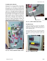
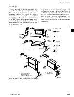
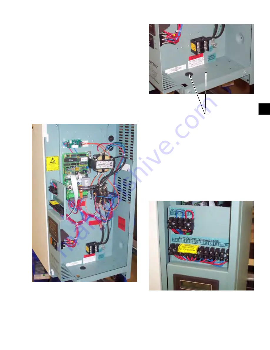
Power options. Fig. 2-62 represents a typical electric
humidifier panel layout. The supply power knockout
is located in the bottom of the electrical panel as seen
in Fig. 2-63. All conduit beginning or ending inside
pressurized or conditioned areas (i.e. air handler) must
have all openings of conduit sealed to prevent air from
passing through. All air handling unit penetrations
must be sealed to prevent air and water leakage
(see
IOM Section 5 “Penetrations and Grommet Details”)
.
Field provided disconnects must provide circuit
protection according to the humidifier nameplate. All
field wiring to the humidifier must be in accordance
with NEC and local codes and by laws.
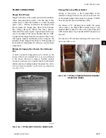
Fig. 2-62 – tYPiCAl huMidiFiER PAnEl lAYOut
LD11726
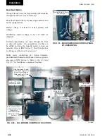
Fig. 2-63 – SuPPlY POWER KnOCKOutS
Humidifier Option
Control wiring diagrams are located in the humidifier
manufacturer's IOM found inside control panel or
attached. Factory package control drawings may not
include humidifier points.
If humidifier IOM cannot be located inside humidifier,
call Johnson Controls Airside Product Support for
information on receiving an electronic version of the
IOM.
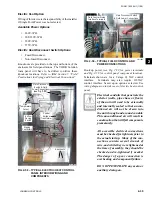
Fig. 2-64 – huMidiFiER POintS
KNOCKOUTS
LD11727
LD11725
Summary of Contents for YORK SOLUTION LD09624
Page 4: ...johnson controls 4 FORM 102 20 N1 1109 THIS PAGE INTENTIONALLY LEFT BLANK ...
Page 10: ...johnson controls 10 FORM 102 20 N1 1109 THIS PAGE INTENTIONALLY LEFT BLANK ...
Page 16: ...johnson controls 16 FORM 102 20 N1 1109 THIS PAGE INTENTIONALLY LEFT BLANK ...
Page 30: ...johnson controls 1 8 FORM 102 20 N1 1109 THIS PAGE INTENTIONALLY LEFT BLANK ...
Page 106: ...johnson controls 2 76 FORM 102 20 N1 1109 THIS PAGE INTENTIONALLY LEFT BLANK ...

