2-15
johNSoN coNtroLS
ForM 102.20-N1 (1109)
2
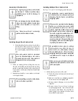
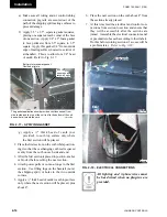
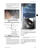
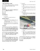
After wiring connections are made
and before proceeding with assembly,
the top shipping split angle will need
to be removed and repositioned (see
Fig. 2-19).
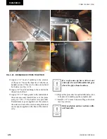
8. Attach the power pulls or come-a-longs to the far
end of the next section.
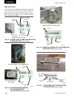
Fig. 2-19 – REMOVE And REPOSitiOn ShiPPing
SPlit AnglE
Remove Shipping Split Angle
after completion of wiring and
tubing placement and
reposition before proceeding
with assembly of shipping
splits.
Remove Shipping Split Angle
after completion of wiring and
tubing placement and
reposition before proceeding
with assembly of shipping
splits.
LD14097
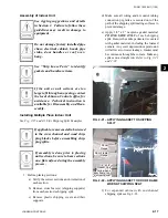
Ensure chain does not apply pressure
to drain connection. Improper posi-
tioning of chain may cause damage
to unit.
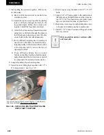
9. Start pulling this section toward the first section.
Pull evenly on both sides.
a) Be sure all of the electrical or control wires
or tubes are clear.
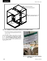
b) Guide the top raceways together by placing
rods or drift pins through the holes in the top
guide angles. When the raceways are close
enough, install the long bolts provided.
c) Guide the bottom raceways together using
rods or drift pins through the bolt holes in
the lifting lugs on opposite sections. Do this
on each side of the unit simultaneously.
d) If any difficulty aligning due to racking of
one section or the other, use another come-a-
long diagonally on the inside of that section,
at or close to the shipping split. Straps may
be used across the unit roof.
e) If any difficulty due to top and bottom not
pulling together evenly or simultaneously,
the curb is probably not installed flat. Apply
shims under the curb or roof decking to
compensate for irregularities of the roof
deck.
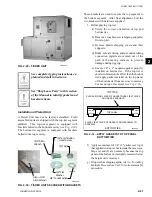
10. Complete pulling the sections together.
Use come-a-longs to pull the sections
together. The bolts are to hold the
sections tight after they are pulled
together.
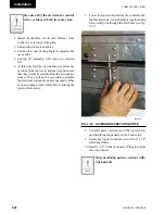
11. Fasten bottom lifting lugs together using 1/2" x
4" bolts provided.
12. Fasten top raceway bracket using 1/2" x 5-1/2"
bolts.
Summary of Contents for YORK SOLUTION LD09624
Page 4: ...johnson controls 4 FORM 102 20 N1 1109 THIS PAGE INTENTIONALLY LEFT BLANK ...
Page 10: ...johnson controls 10 FORM 102 20 N1 1109 THIS PAGE INTENTIONALLY LEFT BLANK ...
Page 16: ...johnson controls 16 FORM 102 20 N1 1109 THIS PAGE INTENTIONALLY LEFT BLANK ...
Page 30: ...johnson controls 1 8 FORM 102 20 N1 1109 THIS PAGE INTENTIONALLY LEFT BLANK ...
Page 106: ...johnson controls 2 76 FORM 102 20 N1 1109 THIS PAGE INTENTIONALLY LEFT BLANK ...

