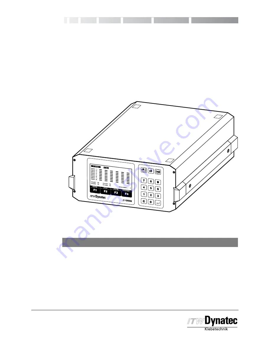
ITW Dynatec DY 2008 Operating Manual Download Page 1

DY 2008

Pattern Controller

CONTROLLER

Operating Manual

2008 D.BOO 11/02

ITW Dynatec

An Illinois Tool Works Company

31 Volunteer Drive

Hendersonville, TN 37075 USA

Tel1 615 824 3634

FAX +1 615 264 5222

dynatec@itwdynatec.com

www.itwdynatec.com

ITW Dynatec K.K.

Daiwashinagawa Bldg., 7-15 Konan, 3-Chome

Minata-Ku, Tokyo 108 Japan

Telephone 81 3 3450 5901

FAX 81 3 3450 8405

info@itwdynatec.co.jp

ITW Dynatec

Industriestraße 28

40822 Mettmann, Germany

Tel.: +49 (0)2104 915-0

FAX: +49 (0)2104 / 915 111

info@itwdynatec.de

Manual #50-14

Rev.11/15

For an online copy of this manual, go to www.itwdynatec.com/manuals.htm

Summary of Contents for DY 2008

Page 1: ...5222 dynatec itwdynatec com www itwdynatec com ITW Dynatec K K Daiwashinagawa Bldg 7 15 Konan 3 Chome Minata Ku Tokyo 108 Japan Telephone 81 3 3450 5901 FAX 81 3 3450 8405 info itwdynatec co jp ITW Dynatec Industriestraße 28 40822 Mettmann Germany Tel 49 0 2104 915 0 FAX 49 0 2104 915 111 info itwdynatec de Manual 50 14 Rev 11 15 For an online copy of this manual go to www itwdynatec com manuals h...

Page 2: ......

Page 3: ......

Page 4: ......

Page 5: ... Panel 4 1 Remote Purge Control 4 2 Service Settings Menus 4 3 Production Setup Menu 4 4 Power On and Software Version 4 5 Service Settings 4 6 Service Settings Menu 1 of 3 Overview 4 6 Service Settings Menu 2 of 3 Overview 4 8 Service Settings Menu 3 of 3 Overview 4 9 Factory Defaults 4 9 Service Setting Programming Conventions 4 11 Display Contrast Adjustments 4 11 Service Settings Menu 1 4 12 S...

Page 6: ...ction 4 44 Pressure Adjustment 4 45 Adjust Minimum Pressure 2 Point Curve 4 45 Adjust Maximum Pressure 2 Point Curve 4 45 Adjust Purge Pressure 2 Point Curve 4 46 Assigning the Pressure Points to the Machine Speed 12 Point Curve 4 46 Adjust Purge Pressure 12 Point Curve 4 47 System Menus Dot Function Stitching and Head Position 4 48 Dot Configuration 4 48 Stitching Configuration 4 50 Offset Head P...

Page 7: ...l should be kept with the installed system as reference material Proper Use of the System This controller is designed for use only with ITW Dynatec hot melt or cold glue systems Other applications should be attempted only after consulting with ITW Dynatec Manual Symbols Caution This symbol means that failure to observe the specific instructions could cause damage to the equipment Danger High Volta...

Page 8: ...rs as a result of using parts that are not factory recommended Working with the Cover Open Never operate this controller with open cover There are no servicable components inside All settings are done via Software Inside the controller are electric current carrying components To avoid personal injury do not touch them while input power is ON Disconnect and lockout main power before opening the cov...

Page 9: ...t melt and cold glue The speed of the production machine will be registered with up to four encoders and indicated on the display It can be used to control the speed of one or more gear pumps of adhesive supply units or to control the glue pressure on a cold glue system via I P or U P transducers Every time the machine speed varies the glue pressure will follow Working with four encoders enables a...

Page 10: ...n multiple Triggers can be combined Trigger Lock 0 8000 mm 0 01 to 80 00 in Encoder Max Number 4 Input connectors X17 and X18 24 V DC max 100 mA NPN scalable Assignment Any encoder can be assigned to any channel Configuration Metric or inch Scaling 1 4000 pulse m 0 01 99 99 pulse inch Indication of Production Machine Speed max 1200 m min 2000 pulses m 4000 ft min 50 pulses inch Speed Configuration...

Page 11: ...chine speed between Vmin and Vmax Continuous Gluing with Low Speed Continuous gluing starts at machine speed between Vmin and Vmax no trigger input is required Glue Pattern Maximum selectable Pattern and Delay Length 0 8000 mm in steps of 1 mm 0 80 00 inch in steps of 0 01 inch Stitching Glue Bead and Break Length 1 200 mm in steps of 1 mm 0 01 2 00 inch in steps of 0 01 inch Dot Mode Breaks 1 800...

Page 12: ...345 mm 14 150mm 6 F1 F2 F3 F4 DY 2008 Kanal 1 Kanal 2 Kanal 3 Kanal 4 Kanal 5 Kanal 6 Kanal 7 Kanal 8 MUSTER DRUCK SYSTEM KOMPENSAT 0 m min Druck1 0 Druck2 0 Druck3 0 Druck4 0 Programm 1 241 3mm 9 5 279 4mm 11 Operating and Connecting Elements Basic Version Operating Panel Connectors Main Switch Power Inlet ...

Page 13: ... to 8 Shield X9 X16 Trigger 1 to 8 GND 24 V Signal NPN PNP X17 Encoder 1 and 3 GND 24 V Encoder 1 Encoder 3 X18 Encoder 2 and 4 GND 24 V Encoder 2 Encoder 4 X19 Machine contact GND Signal NPN X20 Trigger for Shutter Control GND 24 V Signal NPN PNP X21 Alarm Zero Speed N O Common N C X21 Stop System Ready N O Common N C X22 Not Used X23 Shutter Output Shield X24 X27 Pressure Control Output GND 0 4 ...

Page 14: ...eptacles 2 Engage the locking ring 1 of the connector plugs to the receptacles 3 Connect the controller to the power supply Locating an Optical Trigger Sensor Use the information below to assist in the proper location of an optical triggering device TRIGGER LOCATION GUIDELINES All Conditions Must Be Met All Intermittent Modes Except RANDOM RANDOM Mode D L On Compensation D L On Compensation D Repe...

Page 15: ... the four and eight channel units and is standard for 12 or more channel units 2 Remote Purge Control 28 11101 602 this allows one person operation of the manual gluing purge function at distances up to 10 meters 33 feet from the Main Control Unit or Remote Front Panel if installed 3 Data Interface Option 28 00005 107 this provides the ability to control the programming of the DY2008 from another ...

Page 16: ...Manual 50 14 Revised 8 2008 Installation 3 4 C 2002 PC DY 2008 Purge Control Magnet mount Connecting Options Directly to Control Unit ...

Page 17: ...C DY 2008 Purge Control Attach terminal to ground wire Turn mounting clip clockwise in slot Magnet mount Ground Wire Mounting Clip used for panel mounting Connecting Options Through Remote Front Panel Remove screw to attach Mounting Bracket Remote Panel Mounting Bracket Data Cable ...

Page 18: ...Manual 50 14 Revised 8 2008 Installation 3 6 C 2002 ITW Dynatec An Illinois Tool Works Company Adhesive Application Solutions ...

Page 19: ... Outputs PRESSURE S Trigger Indication for Standard Mode Gluing C Trigger Indication for Continuous Mode Gluing D Trigger Indicator for Dot Mode Gluing R Trigger Indication for Random Mode Gluing Encoder 3 Encoder 4 COM STOP Function Keys F1 F2 F3 F4 These keys can have changing functions The lower line of the display above the keys will indicate the current function Manual Gluing Purge Button Thi...

Page 20: ...sure output circuitry X24 through X27 to output programmed PURGE PRESSURE when STOP is activated STOP activation is indicated by an amber LED that is continuously illuminated See the section of this chapter on Stop Conditions for more detail Deactivating STOP will also automatically cease manual gluing operations on any channels that are still active Manual Gluing Purge Button Used to activate amb...

Page 21: ...ITY LOCK RETURN 0 m min 1 2 3 4 5 6 7 8 9 SERVICE SETTINGS 3 OF 3 STOP 123 CONTRAST CONTRAST STOP Manual 50 14 Revised 8 08 Page 4 3 C 1998 Service Setting Menus Changing these settings may be neccesary during initial installation or after modification to the system After pressing the Stop button these menus are selectable with the Service button The following settings are some of the available se...

Page 22: ...Main Menu appears after a few seconds Display shows machine speed and glue pattern Pressure and program number Glue Pattern Set up Pressure Configuration Linear Pressure Configuration 12 Point Curve Valve Compensation Stitching Configuration or Head Position Dot Configuration System Configuration Menu Structure of the Production Settings ...

Page 23: ...PRESS1 0 PRESS2 0 PRESS3 0 PRESS4 0 PROGRAM 1 Channel 8 1 0 m min Manual 50 14 Revised 8 08 Page 4 5 C 1998 Power Switch On and Software Version Indication The main power switch is located at the back side of the controller After the controller is switched on the display shortly indicates the ITW Dynatec logo and the Software revision After a few seconds the screen will display the Main Menu ...

Page 24: ...inputs are active 4 Trigger Lock This function determines for what length of distance after a trigger signal additional trigger signals will be ignored This function can be necessary gluing products with cut outs e g envelopes with window This will prevent the detection of the window from triggering a new glue cycle It is possible to select values between 1 and 9999 mm 0 01 and 99 99 inch 5 Channe...

Page 25: ...rity Lock This menu is used to lock individual functions to prevent unauthorized modification Additionally it is possible to change the access code You can lock unlock every above mentioned function After locking these functions are only available via access code Locking Unlocking is only possible if you know the access code ...

Page 26: ...ssure Curve Use this menu to select between 2 or 12 point pressure curve 5 Spike Voltage You can select the overexcitation voltage 55V or 170V for each channel or you can deactivate the overexcitation for this channel 6 Spike Duration The duration time of the overexcitation is programmable between 0 5ms and 2 5ms 7 Shutter Assignment Use this menu to assign the shutter output X23 to one of the tri...

Page 27: ...rogram After entering the access code the active program will be reset to the values listed below 9 Change Security Lock This menu is used to lock individual functions to prevent unauthorized modification Additionally it is possible to change the access code You can lock unlock every above mentioned function After locking these functions are only available via access code Locking Unlocking is only...

Page 28: ...vice Settings Menu 3 of 3 No Function Setting 1 STOP Configuration All Channels NOT FINISH GLUING UPON RESTART 2 PC Communication As previously programmed 3 Reserve not used Function locked 4 Shutter Trigger Setting NPN 5 Reserve not used Function locked 6 Digital Configuration Machine Contact Normally Open Relay 1 Stop Relay 2 Alarm 7 Reserve not used Function locked 8 Load Factory Default Functi...

Page 29: ... to enter the desired value The enter icon is displayed in the lower right corner of the screen to indicate that the ENTER button see page 4 1 should be pressed in order to accept the selected value Press the CLEAR Button on the numeric keypad to revert a modified parameter to its original value provided the ENTER button has not already been pressed Press the RETURN F4 button to go to the next hig...

Page 30: ...ible after activating the STOP Button After the controller is switched on the display shortly indicates the ITW Dynatec logo and the Software revision After a few seconds the display changes to the Main Menu That means glue pattern pressure and program number will be shown Press the STOP Button Press the Service Button Select one of the listed functions by pressing the corresponding numeric key No...

Page 31: ...123 RETURN Manual 50 14 Revised 8 08 Page 4 13 C 1998 Press Button F4 to return to previous menu Load Program Use this menu to load a new program or reload a previously stored program Press Button 2 Enter Access Code if this function is protected Press Enter button Select one of the 60 possible programs using the numeric keys Note Loading a program the first time causes all parameters from the pre...

Page 32: ...Press Button 3 Enter Access Code if this function is protected Press Enter Button Select a channel with buttons F1 and F2 With Button F3 you can select a trigger Master Triggers 1 to 4 or Channel Trigger for channels 5 and greater for the selected channel or you can deactivate this channel Press F1 if you want to combine this trigger with another trigger using the AND function NOTE Select AND trig...

Page 33: ...le Press button 4 Select a channel using buttons F1 or F2 Press button F3 to highlight the Trigger Lock value for the selected channel Use the numeric keys to enter the distance you want to ignore trigger signals after a valid trigger has been registered Press Enter button Use F1 or F2 to select another channel Repeat previous steps for this channel Press F4 to return to previous menu Channel Enco...

Page 34: ...want to assign to this channel Encoder 1 to 4 Press Enter button Note For each of the selected encoders the corresponding machine speed will appear in the upper status lines of the display Use F1 or F2 to select another channel Repeat previous steps for this channel Press F4 to return to previous menu CHAN 1 2 3 4 STOP 1 0 m min ENCODER EN 1 EN 1 1 EN 1 EN 1 ZURUECK EN 1 RETURN CHAN 1 2 3 4 STOP 1...

Page 35: ...7 8 9 Code STOP 1 0 m min SERVICE SETTINGS 1 OF 3 123 2 0 m min 3 0 m min 4 0 m min RETURN Manual 50 14 Revised 8 08 Page 4 17 C 1998 Encoder Scaling Use this menu to configure the encoder that is installed by programming the number of pulse per meter inch If the metric unit is selected all distances will be shown in mm and all speed indications will be shown in m min If inch is selected all dista...

Page 36: ...NG STARTS ABOVE GLUING STOPS BELOW MAXIMUM MACHINE SPEED 10 35 600 m min m min m min STOP 1 0 m min 2 0 m min 3 0 m min 4 0 m min MIN MAX SPEED SETTING MENU ENCODER 1 123 Page 4 18 Manual 50 14 Revised 8 08 C 1998 Min Max Speed Configuration This menu determines the speed conditions for start and stop of gluing The start is valid for increasing speed and stop for decreasing speed Additionally the ...

Page 37: ...n can be stitched Pattern is started with trigger signal and minimum machine speed Standard with Dot Up to 16 patterns per trigger input Pattern can be stitched above GLUE STOPS BELOW speed Pattern is started with trigger signal Dot mode is active between GLUE STARTS ABOVE and GLUE STOPS BELOW speeds Dot Up to 16 patterns per trigger input All patterns are user programmable dots Pattern is started...

Page 38: ... CHANNEL TRIGGER TRIGGER LOCK CHANNEL ENCODER ENCODER SCALING MIN MAX SPEED SET CHANNEL MODE CHANGE SECURITY LOCK 1 2 3 4 5 6 7 8 9 Code STOP 1 0 m min SERVICE SETTINGS 1 OF 3 123 2 0 m min 3 0 m min 4 0 m min Page 4 20 Manual 50 14 Revised 8 08 C 1998 Press button 8 Enter Access Code if this function is protected Press Enter Button Use button F1 or F2 to select a channel Press button F3 to change...

Page 39: ...andom Length Mode incorporates a time out function to prevent excessive undesired glue flow in the event of a product jam under the triggering device Set this value to be slightly greater than the longest anticipated time by taking into account the longest product and slowest production speeds Press F1 to enter the Time Out Menu Use the F3 button to select the existing time value Enter the desired...

Page 40: ...ed 8 08 C 1998 Change Security Lock In this menu it is possible to lock individual functions to prevent unauthorized modification Additionally it is possible to change the access code You can lock unlock every above mentioned function After locking these functions are only available via an access code Locking Unlocking is possible only if you know the access code Press button 9 Enter Access Code P...

Page 41: ...you see the menu at right Use the buttons 1 to 9 to select one of the listed functions Trigger Setup Use this menu to select the properties of the trigger devices used NPN or PNP Press button 1 Enter Access Code if this function is protected Press Enter Button Use button F1 or F2 to select a trigger input Press button F3 to change the trigger type from NPN to PNP and vice versa Press Enter button ...

Page 42: ... 123 2 0 m min 3 0 m min 4 0 m min Page 4 24 Manual 50 14 Revised 8 08 C 1998 Press F4 to return to previous menu Pressure Signaling Use this menu to configure the pressure control outputs Press button 2 Enter Access Code if this function is protected Press Enter Button Note Refer to the data sheet of the I P or U P transducer for proper setting Press F1 or F2 to select the pressure output 1 X24 2...

Page 43: ...ders or to shut the output off Press button 3 Enter Access Code if this function is protected Press Enter Button Use buttons F1 or F2 to select the pressure output Press button F3 to select the encoder you want to assign the pressure output to or to shut the output off Confirm the selection with the Enter button and repeat the procedure for the next pressure output Press F4 to return to previous m...

Page 44: ...r 12 point pressure curves Press button 4 Enter Access Code if this function is protected Press Enter Button Press F1 or F2 to select a pressure output Use button F3 to toggle between 2 point and 12point pressure curve Confirm the selection with the Enter button and repeat the procedure for the next pressure output Press F4 to return to previous menu STOP 1 0 m min 2 0 m min 3 0 m min PRESSURE CUR...

Page 45: ...his setting is appropriate for the equipment used in your system If necessary change this value Note ITW Dynatec DynaCold Series applicators must always be operated with 170V spike voltage Press button 5 Enter Access Code if this function is protected Press Enter Button Use button F1 or F2 to select a channel Press button F3 to choose the spike voltage of 55V 170V or OFF Press Enter button and rep...

Page 46: ... protected Press Enter Button Note Time values range from 0 50 to 2 50ms 1 60ms default is recommented for most applications Use button F1 or F2 to select a channel Press button F3 to switch to the spike time field Press button F1 to increase the spike duration time by a step of 0 05 ms Press button F2 to decrease the spike duration time by a step of 0 05 ms or Use the numeric buttons to enter the...

Page 47: ...age 4 29 C 1998 Shutter Assignment Use this menu to assign the shutter output X23 to one of the triggers Press button 7 Enter Access Code if this function is protected Press Enter Button Press button F3 to assign the shutter to one of the Master triggers IN1 to IN4 X9 thru X12 or to a dedicated input INS X20 Press Enter Button Press F4 to return to previous menu STOP 1 0 m min 2 0 m min 3 0 m min ...

Page 48: ...djustment This menu adjusts the duration of time the shutter circuit remains active after the last trigger input Press button 8 Enter Access Code if this function is protected Press Enter Button Press button F3 to switch to the dwell time field Use the numeric keys to enter the dwell time The valid range is 1 to 99 seconds Press Enter Button Press F4 to return to previous menu STOP 1 0 m min 2 0 m...

Page 49: ...min 3 0 m min 4 0 m min Manual 50 14 Revised 8 08 Page 4 31 C 1998 Change Security Lock In this menu it is possible to lock individual functions to prevent unauthorized modification Additionally it is possible to change the access code You can lock unlock every above mentioned function After locking these functions are only available via an access code Locking Unlocking is possible only if you kno...

Page 50: ...STOP Configuration This function determines the behavior of the controller in case of a restart after a stop of the production machine In most cases a restart will start gluing with the next trigger Some special applications require the current glue pattern to be completed before starting with the next product Press button 1 Enter Access Code if this function is protected Press Enter Button Use bu...

Page 51: ... functional only when the Data Option X30 has been installed Press button 2 Enter Access Code if this function is protected Press Enter Button Use buttons F1 or F2 to select the item to be changed Press buttons F2 or F3 to change the selected item Press Enter Button Repeat this procedure for each parameter to be changed Note If the RS485 Interface is activated the Slave Address is adjustable Press...

Page 52: ...d 8 08 C 1998 Enter Access Code if this function is protected Press Enter Button Enter the desired Profibus Address via the numeric keypad Press Enter Button Press F4 to return to previous menu Shutter Trigger Setup Use this menu to select the properties of the dedicated shutter trigger device X20 as being either NPN sink ing or PNP sourcing Press button 4 Enter Access Code if this function is pro...

Page 53: ...to be changed Use the F3 button to highlight the current value Use the F1 or F2 Button to change the para meter to the desired value Value descrip tions are as follows Machine Contact X19 The machine contact provides a means of disabling the pattern control drive outputs via a customer supplied external relay EXTER STOP is displayed at the top center ofthecontrolunitdisplaywhenthedriveout puts hav...

Page 54: ... page 3 1 Connectors and Contact Defini tions of this manual for wiring specifica tions Possible settings are described be low FUNCTION RELAY 1 STOP The relay is triggered each time a stop condition i e STOP BUS STOP COM STOP COM2 STOP or EXTER STOP occurs SYSTEM READY The relay is triggered each time a stop condition i e STOP BUS STOP COM STOP COM2 STOP or EXTER STOP or zero speed condition oc cu...

Page 55: ...ry defaults Press Enter Button after entering Access Code Note You cannot recover programmed informa tion once the Enter button is pressed The following factory defaults will be loaded Factory Default Values Service Settings Menu 1 of 3 No Function Setting 1 Language English 2 Program As per operator selection 3 Trigger Assignment All Channels are assigned to Trigger 1 The AND function is deactiva...

Page 56: ...vice Settings Menu 3 of 3 No Function Setting 1 STOP Configuration All Channels NOT FINISH GLUING UPON RESTART 2 PC Communication As previously programmed 3 Profibus Address if installed As previously programmed 4 Shutter Trigger Setup NPN 5 Reserve not used Function locked 6 Digital Input Output Contact N O Relay 1 STOP Relay 2 ALARM 7 Reserve not used Function locked 8 Load Factory Default Funct...

Page 57: ...NGS 3 OF 3 Manual 50 14 Revised 8 08 Page 4 39 C 1998 Change Security Lock In this menu it is possible to lock individual functions to prevent unauthorized modification Additionally it is possible to change the access code You can lock unlock every above mentioned function After locking these functions are only available via access code Locking Unlocking is only possible if you know the access cod...

Page 58: ...in Menu appears after a few seconds Display shows machine speed and glue pattern Pressure and program number Glue Pattern Set up Pressure Configuration Linear Pressure Configuration 12 Point Curve Valve Compensation Stitching Configuration or Head Position Dot Configuration System Configuration Menu Structure of the Production Settings ...

Page 59: ...Activating the Stop function on the DY2008 disables all drive outputs Stop may be activated through any of five means 1 Pressing the STOP button in the top right corner of the front panel in which case the word STOP is flashing in the top center of the display screen 2 Pressing the STOP button on the optional Remote Purge Control device 28 11101 602 in which case the words COM2 STOP are flashing i...

Page 60: ...case the words BUS STOP are flashing in the top center of the display screen The Stop Function may be activated by more than one of the above sources simultaneously Any sources that have activated the Stop Function must also be used to deactivate the Stop Function Deactivation is accomplished by reversing the process used to activate NOTE STOP may be activated via the DY2008 front panel from any o...

Page 61: ...glue pattern For example minimum value for Delay 2 Delay 1 Glue 1 1mm 0 01 in If neccesary procede in the same way for additional glue patterns Note If a channel is set for Random Length Mode it is only possible to adjust the start delay unglued margin and end delay distance between end of glue bead and end of product Note If a channel is set for continuous mode no pattern settings are adjustable ...

Page 62: ...tion of a channel s delay and glue values to be copied These values can then be easily pasted to other channels Completely program a channel that is to be copied as per the instructions provided in the previous section Once the channel has been programmed press the F1 button to copy the delay and glue values programmed in that channel Press the F4 button once Use the F1 or F2 buttons to select ano...

Page 63: ...ew seconds after switching on the pattern controller If you are in a different menu press F4 RETURN as many times as necessary to return to the Main Menu as shown at right Press button F2 Use button F3 to select a Pressure Output Note Depending on whether a 2 Point or 12 Point Pressure Curve is selected for the particular pressure output X24 thru 27 Service Setting Menu 2 of 3 Function 4 different...

Page 64: ...n Procede with addtional adjustment in the same way Assigning the Pressure Points to the Machine Speed 12 Point Curve Assumption for this menu the selected output has been set to 12 Point Curve in the Service Setting Menu 2 of 3 Function 4 The upper lines in this table show the machine speed The lower lines show the corresponding output pressure in percent It is possible to randomly adjust the val...

Page 65: ...RN PRESSURE SYSTEM COMP 1 0 m min PRESS1 0 PRESS2 0 PRESS3 0 PRESS4 0 PROGRAM 1 2 0 m min 3 0 m min 4 0 m min Manual 50 14 Revised 8 08 Page 4 47 C 1998 Purge Pressure Adjustment 12 Point Curve Press button F1 or F2 until the Purge Pressure value is highlighted Use the numeric keys to enter the pressure for manual gluing e g 80 Select the next pressure output using the F3 button Procede with addti...

Page 66: ...o adjust the Dot Configuration Stitching and Head Position Offset parameters Dot Configuration The ability to enter the Dot Configuration Menu is offered when one of the dot modes i e STANDARD WITH DOT or DOT have been selected in the Service Settings Menu 1 of 3 Function 8 Press button F1 from the SYSTEM MENU Only those channels with modes programmed for dots see above will be displayed Use the F...

Page 67: ... that the glue applicator will be turned on to produced the dot Use the numeric keypad or the F1 F2 buttons to enter the desired value for GLUE The F1 F2 buttons will increment decrement the GLUE value in 0 10 millisecond steps as a fine tuning adjustment capability Press the F4 button then select the next channel Repeat the above procedures for each channel Press the F4 button to return to the Sy...

Page 68: ...min 0 m min C 1 C 2 C 3 C 4 C 5 C 6 C 7 C 8 STITCH MENU mm GLUE GAP 4 4 4 4 4 4 4 4 4 4 4 4 4 4 4 4 123 Page 4 50 Manual 50 14 Revised 8 08 C 1998 Stitching Configuration Press button F2 Use buttons F1 or F2 to select a channel Select a glue event pattern using the button F3 Note Selected glue event is indicated at the bottom of the display CURRENT GLUE EVENT X Press button F1 to activate or deact...

Page 69: ... 3 C 4 C 5 C 6 C 7 C 8 SYSTEM MENU DOTS Manual 50 14 Revised 8 08 Page 4 51 C 1998 Use the numeric keys to enter the glue length for the stitching mode e g 2mm Note The smallest unit is one encoder pulse e g Encoder scaling 1000pulses m 1mm The stitching glue length should not exceed the length of the glue pattern Press button F3 Use the numeric keys to enter the stitching gap e g 2mm Press button...

Page 70: ...ator head and trigger device for every channel The shown display appear a few seconds after switching on the pattern controller If you are in a different menu press F4 RETURN as many times as necessary to return to the Main Menu as shown at right Press button F3 Press button F3 Use buttons F1 and F2 to select a channel Press button F3 Use the numeric keys to enter the distance between applicator h...

Page 71: ... 6 C 7 C 8 PATTERN PRESSURE SYSTEM COMP 1 0 m min PRESS1 0 PRESS2 0 PRESS3 0 PRESS4 0 PROGRAM 1 2 0 m min 3 0 m min 4 0 m min Manual 50 14 Revised 8 08 Page 4 53 C 1998 Press button F4 Select another channel using buttons F1 and F2 and repeat procedure for these channels in the same way Press F4 to return to System Menu Press F4 to return to Main Menu ...

Page 72: ...djustment The shown display appear a few seconds after switching on the pattern controller If you are in a different menu press F4 RETURN as many times as necessary to return to the Main Menu as shown at right Press button F4 Use buttons F1 and F2 to select a channel Press button F3 Measure the start delay the distance between where the glue bead should start and where it actually starts of the gl...

Page 73: ...08 automatically adjusts its pressure outputs X24 through X27 to the programmed PURGE PRESSURE see Pressure Adjustment in this chapter upon entering the Manual Gluing menu The PURGE PRESSURE outputs will remain active until the MANUAL GLUING menu is exited at which time the output pressures revert back to levels as programmed in the 2 Point or 12 Point pressure menus Manual Gluing may be accomplis...

Page 74: ...for all channels simultaneously Press F4 to exit the Manual Gluing menu Keep in mind the following 1 Manual Gluing will be active only as long as the F3 ON button is depressed unless it is locked on by simultaneously depressing the F3 ON and F1 LOCK buttons It is pos sible to simultaneously activate any number of channels in this manner 2 Any active channels will automatically be deactivated upon ...

Page 75: ...nction of the Remote Purge Control COM2 STOP will be displayed at the top center of the DY2008 display i e main control unit when the Remote Purge Control activates STOP as long as STOP has not also been activated from any other source see STOP FUNCTION in this chapter Press the Increment or Decrement button to select the desired channel for manual gluing as indicated in the LED display at the top...

Page 76: ...t the DY2008 pressure control circuitry X24 through X27 automatically outputs the programmed PURGE PRESSURE when STOP is activated via the Remote Purge Control The purge pressure output remains active until the Remote Purge Control stop condition is deactivated ...

Page 77: ...ror Messages of the DY2008 Controller Communication Error This is an internel error that can only be repaired by ITW Dynatec personnel In this case consult with the Technical Service Department Over Current Failure An output channel of the controller has registered excessive overload The display will show the corresponding channel number Troubleshoot according to the table on the following page Co...

Page 78: ...l Technical service department Over Current Failure Chan x Short Circuit in cable or connection between controller and solenoid Switch Off controller and check cables and connections Replace if damaged Short Circuit in solenoid Switch Off controller and check solenoid Replace if necessary Internal Short Circuit Switch Off controller and call Technical Service Department ...

Page 79: ...t Cables 7 05 01004 605 Drive Cable Assembly Unterminated 5M 8 05 01004 610 Drive Cable Assembly Unterminated 10M 9 05 02104 616 Drive Cable Assembly 9 4mm DIN 2pole 5M 10 05 02104 622 Drive Cable Assembly for Macon Head 5M 11 05 02104 624 Drive Cable Assembly for Macon Head 10M 12 05 03104 000 Y cable for connecting two solenoids not for DynaCold or Macon applicators 11 05 02104 100 Drive Cable E...

Page 80: ...ble 10M 28 28 20000 004 Y Cable to Connect Encoders 3 or 4 29 05 02104 610 Y Cable to Connect one encoder to two inputs Pressure Control Accessories 30 05 67000 705 I P Transducer Kit includes one 05 67000 102 see below 31 05 67000 706 I P Transducer Kit includes two 05 67000 102 see below 32 05 67000 102 I P Transducer EIT201 002B with 5M cable 33 05 67000 706 I P Transducer EIT601 000 with 5M ca...

Page 81: ...ITW Dynatec c 2003 Appendix A pg 3 DY2008 Controller Manual 50 14 Revised 2 05 42 109225 M12 Male 43 109223 M12 Female Fuses 44 111305 Fuse 4 0A 20mm 45 111306 Fuse 3 15A 20mm ...

Page 82: ...Appendix A pg 4 ITW Dynatec c 2003 Revised 2 05 DY2008 Controller Manual 50 14 ITW Dynatec c 2005 ...

Page 83: ...ct the printed circuit boards of the DY2008 in full detail Removing PC Boards from Card Cage Power Supply Board 28 00001 100 The Power Supply Board regulates the DC voltage withing the Pattern Control There is one of these boards for each eight drive output channels i e each two Driver Cards in the DY2008 See illustration of board on the following page f DANGER Place this control Unit in a dry and...

Page 84: ...ion Designation Voltage Function LED 1 24VDC Drive Output Voltage LED 2 55VDC Drive Output Voltage LED 3 170VDC Drive Output Voltage LED 4 24VDC Encoder Triggers Pressure Control Voltage LED 5 5VDC Microprocesssor Control Voltage Fuses The only fuses in the DY2008 Control Unit are located on the Power Supply Board There are a total of six fuses on this board each covered by a plastic shield protec...

Page 85: ...ies output 24VDC 55VDC or 170VDC for up to four channels within the Control Unit There is one of these boards for each four output channels of the unit It is important when installing these cards to assure the DIP Switch A1 positions one through four are all turned ON for the Driver Card used for channel outputs 1 through 4 Driver Card 1 All other Driver Cards should have all DIP switches set to t...

Page 86: ... must be properly set for the unit to function Below is a table to indicate the proper DIP Switch settings for different channel capacity units S1 DIP Switch Setting Chart Below is a chart to guide the setting of the S1 DIP Switches based on the number of channels in the Control Unit Note that the number of Communication Boards is cumulative Each preceding board must also be set properly within th...

Page 87: ... off off off off off 17 thru 32 2 on off off off off off off off 33 thru 48 3 off on off off off off off off 49 thru 64 4 on on off off off off off off 65 thru 80 5 off off on off off off off off 81 thru 96 6 on off on off off off off off 97 thru 112 7 off on on off off off off off 113 thru 128 8 on on on off off off off off Electrical Connector Dip Switch S1 Communication Board ...

Page 88: ...Improper connection could result in defective keypad operation DIP Switch S1 All four positions of this switch should be OFF when no Profibus Option is installed Position 1 is turned ON with the others OFF when the Profibus is installed Jumper JP1 The jumper should be on the two right most posts of JP1 during normal operation The third post DNL should be left exposed Communication Board Connector ...

Page 89: ...ides control of the purge function from a distance up to 10M 33 ft from the Operator Interface Unit when used with any version of the DY2008 Pattern Control This is normally a factory installed option consisting of a PC Board with ribbon cable that is installed inside the DY2008 a hand held purge control box and a ten meter 33 ft cable to connect the purge control box to the DY2008 See the chapter...

Page 90: ... with ribbon cable that is installed inside the DY2008 See the chapter on Installation for more details on computer data interface connections RS232 485 Connectors and Jumpers The Computer Data Interface Option board has two 9 pin D connectors mounted on it one marked 485 and one marked 232 Determine which communication protocol is to be used and mount the card into the DY2008 accordingly Likewise...

Page 91: ...ITW Dynatec c 2003 Appendix B pg 9 DY2008 Controller Manual 50 14 Revised 1 09 ...

Page 92: ...Appendix B pg 10 ITW Dynatec c 2003 Revised 1 09 DY2008 Controller Manual 50 14 c 2003 ITW Dynatec ...

Page 93: ...MMING LOG Make Photo Copies of this Log and Use as Necessary Program Production Set Up Menus Pattern DEL 1 GLUE DEL 2 GLUE DEL 3 GLUE DEL 4 GLUE DEL 5 GLUE DEL 6 GLUE DEL 7 GLUE DEL 8 GLUE C1 C2 C3 C4 C5 C6 C7 C8 Pressure OUTPUT 1 MIN MAX PURGE SPEED PRESSURE OUTPUT 2 MIN MAX PURGE SPEED PRESSURE ...

Page 94: ...itch CHANNEL GLUE GAP EVENT S CHANNEL GLUE GAP EVENT S Offset CHANNEL OFFSET CHANNEL OFFSET CHANNEL OFFSET CHANNEL OFFSET Compensation CHANNE L ON COMP OFF COMP CHANNE L ON COMP OFF COMP CHANNE L ON COMP OFF COMP CHANNE L ON COMP OFF COMP CHANNE L ON COMP OFF COMP CHANNE L ON COMP OFF COMP CHANNE L ON COMP OFF COMP CHANNE L ON COMP OFF COMP CHANNE L ON COMP OFF COMP ...

Page 95: ... CHANNEL TRIGGER AND TRIG CHANNEL TRIGGER AND TRIG Trigger Lock CHANNEL LOCK CHANNEL LOCK CHANNEL LOCK CHANNEL LOCK CHANNEL LOCK CHANNEL LOCK CHANNEL LOCK CHANNEL LOCK Channel Encoder CHANNE L ENCODE R CHANNE L ENCODE R CHANNE L ENCODE R CHANNE L ENCODE R Encoder Scaling ENCODER PPI PPM ENCODER PPI PPM ENCODER PPI PPM ENCODER PPI PPM Min Max Speed EN1 EN2 EN3 EN4 GLUE STARTS ABOVE GLUE STOPS BELOW...

Page 96: ...ER NPN PNP TRIGGER NPN PNP TRIGGER NPN PNP TRIGGER NPN PNP TRIGGER NPN PNP Pressure Signaling OUTPUT 0 10V 4 20mA OUTPUT 0 10V 4 20mA OUTPUT 0 10V 4 20mA OUTPUT 0 10V 4 20mA 1 2 3 4 Pressure Assignment OUTPUT ENCODER OUTPUT ENCODER OUTPUT ENCODER OUTPUT ENCODER 1 2 3 4 Pressure Curve OUTPUT 2PT 12PT OUTPUT 2PT 12PT OUTPUT 2PT 12PT OUTPUT 2PT 12PT 1 2 3 4 Spike Voltage CHANNE L VOLTAG E CHANNE L VO...

Page 97: ...R __________ Shutter Dwell Time _________ SECONDS Stop Configuration CHANNE L NOT FINSH FINISH CHANNE L NOT FINSH FINISH CHANNE L NOT FINSH FINISH PC Communication BAUD RATE PORT ADDRESS Profibus Address PROFIBUS ADDRESS _______ Shutter Trigger Setup NPN PNP Digital Configuration MACHINE CONTACT N O N C FUNCTION RELAY 1 STOP SYSTEM READY FUNCTION RELAY 2 ALARM ZERO SPEED ...

Page 98: ...Appendix C pg 6 ITW Dynatec c 2003 Revised 8 08 DY2008 Controller Manual 50 14 c 2003 ITW Dynatec ...

Reviews: