22
Document Number
DCV-00214
Date Released
Mar. 2017
Revision Number/Security level
R00 S2
Retrofit G6+InvencoLink GVR Encore 500S (US) Installation Guide
24.
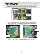
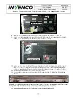
Pull the Printer Cables through the back of the Printer Assembly and lay them inside the
Electronics Cavity.
25.
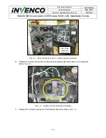
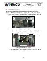
Remove the Ground Screw located on the Electronics Cavity Interior Channel, left of the Printer
Assembly. The Printer Assembly’s Ground Screw is separate and by itself from other grounding
locations inside the Dispenser. The screw can be discarded; it will not be re-installed.
26.
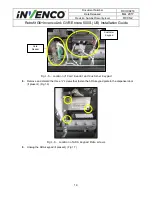
Slide the printer assembly back, so that it does not tip over when the mounting screws are
removed in the next step.
27.
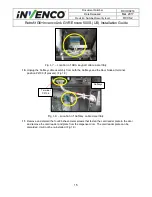
Remove the four mounting screws that are fastening the Printer Bracket to the Electronics Cavity
Frame. Remove the Printer Assembly and screws. They can be discarded; they will not be re-
installed.
28.
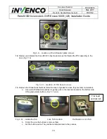
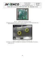
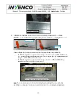
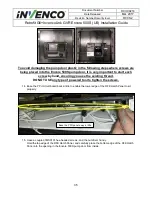
The four holes for the printer mounting must be plugged after its removal. Use the supplied four
MS0166 #10-
32 x ¾” screws for this purpose:
a. If the threads in the holes are intact, start and then tighten the screws in the holes.
b. For any of the holes where the threads are stripped, place an MN0027 #10-32 nut onto
the screw from the outside of the cabinet, and use it to tighten the MS0166 screw.
Note: you may not need all four nuts.
29.
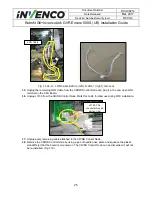
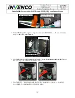
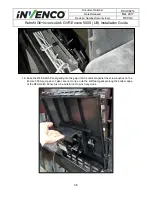
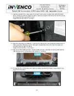
Unplug the USB cable from terminals P3120 for Side-A (P3122 for Side-B) CRIND Control Node,
which is located on the Upper Electronics Mount Rail.
Ground Screw
Printer Assembly
Mounting Screws

