25
Document Number
DCV-00214
Date Released
Mar. 2017
Revision Number/Security level
R00 S2
Retrofit G6+InvencoLink GVR Encore 500S (US) Installation Guide
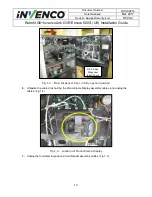
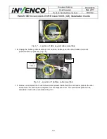
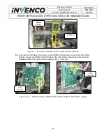
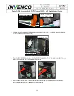
Fig 1.18c,d
–
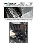
LON Cable before (left) & after (right) removal
35.
Unplug the remaining LON Cable from the CRIND Control Node and plug it in the now open LON
terminal on the CPU Board.
36.
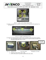
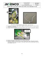
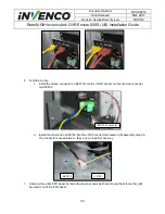
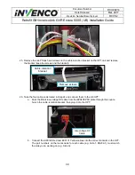
Unplug J3105 from the CRIND Control Node. Mark this cable for later use during RFK installation.
37.
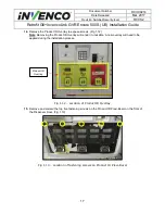
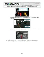
Unplug every remaining cable attached to the CRIND Control Node.
38.
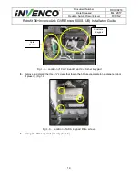
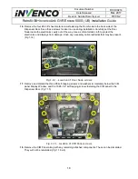
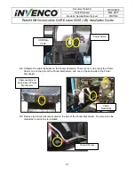
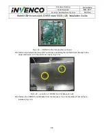
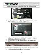
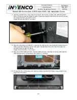
Remove the CRIND Control Node by using a pair of needle nose pliers and squeeze the plastic
standoffs (4) that the board is mounted on. The CRIND Control Node can be discarded. It will not
be re-installed. (Fig 1.19)
LON Cable
J3105. This
connector may be
white or red.

