INSTALLATION / HANDLING
42
SL, SM & SH 90, 110, 132, 150, 200, 250 &300 (50Hz)
L, H & HH 125, 150, 200, 250, 300, 350 & 400 (60Hz)
Revision 01
10/98
T4002
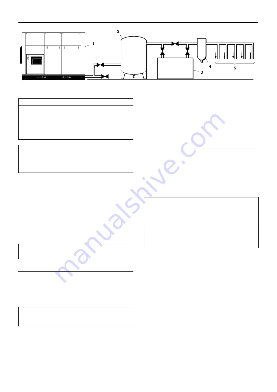
KEY
1. Compressor
2. Air Receiver
3. Air Dryer
4. Compressed air filters
5. System demand points
NOTE:
The diagram above shows two typical simple installations.
Items [2] to [5] are optional or may be existing items of plant. Refer
to your Ingersoll–Rand distributor / representative for specific
recommendations.
COMMISSIONING
Upon receipt of the unit, and prior to putting it into service, it is
important to adhere strictly to the instructions given below in PRIOR TO
STARTING.
Ensure that the operator reads and understands the decals and
consults the manuals before maintenance or operation.
Ensure that the position of the emergency stop device is known and
recognised by its markings. Ensure that it is functioning correctly and
that the method of operation is known.
NOTE
All dimensions are in millimetres unless otherwise stated.
UNPACKING
The compressor will normally be delivered with a polythene cover.
If a knife has to be used to remove this cover ensure that the exterior
paintwork of the compressor is not damaged.
Ensure that all transport and packing materials are discarded.
IMPORTANT
Remove any shipping brackets particularly the soft mount
transit braces painted in primer.
Incorporated within the base of the compressor are slots to enable
a fork lift truck (4 tonnes minimum for 90–150kW, 125–200HP, 8 tonnes
minimum 200–300kW, 250–400HP) to move the machine.
Alternatively a special lifting frame can be supplied to enable a crane
or hoist to move the compressor.
Ensure that the correct fork lift truck slots or marked lifting / tie down
points are used whenever the machine is lifted or transported.
LOCATION IN THE PLANT
The compressor can be installed on any level floor capable of
supporting it. A dry, well ventilated area where the atmosphere is as
clean as possible is recommended.
Ensure that the machine is positioned securely and on a stable
foundation. Any risk of movement should be removed by suitable
means, especially to avoid strain on any rigid discharge piping.
CAUTION: A minimum of 1 metre (3ft) all round the compressor
is recommended (Additional clearance required on water cooled
units for tube bundle removal – see foundation plan). If headroom
is restricted, then the exhaust should be ducted or deflected away
from the machine.
IMPORTANT
If ducting is fitted, the sump breather needs to be piped outside
the enclosure to avoid back pressure into the compression
module.
Sufficient space all round and above the compressor must be
allowed, to enable the effective removal of the cooling air which, in turn,
will reduce the risk of re–circulating the cooling air back through the
compressor.
Adequate clearance needs to be allowed around and above the
machine to permit safe access for specified maintenance tasks.
Hard surfaces may reflect noise with an apparent increase in the
decibel level. When sound transmission is important, a sheet of rubber
or cork can be installed beneath the machine to reduce noise.
It is recommended that provision be made for lifting heavy
components during major overhaul.


