*/%*"/$)*&'7*/5"(&4&37*$&."/6"-
&/(*/&
153
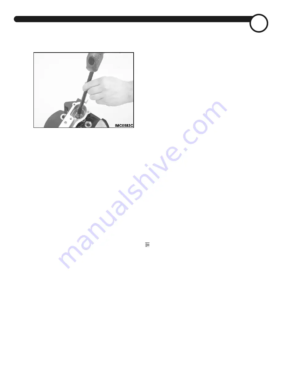
If the valve guide is to be removed, use valve guide
tool, JIMS
®
34740-84, and a hammer to drive the guide
out from the head.
Figure 294 — Removing valve guide
$MFBOJOHBOE*OTQFDUJPO
Clean the cylinder head and all associated parts
including valves with a suitable non-flammable solvent.
Scrape the carbon buildup from any parts using care to
avoid damage. Flush with solvent to remove all traces of
dirt and debris, making sure that all ports, passages,
bores and threads are thoroughly clean. Dry parts with
compressed air.
Inspect the valve stems and faces for wear and damage.
Also, inspect the valve guides and valves seats.
Measure the following to ensure that wear limits are not
exceeded (see Specifications):
•
Cylinder head flatness (gasket surface)
•
Valve seat width
•
Valve stem protrusion from cylinder head
•
Valve-to-guide clearance
If removed from the cylinder head, also measure
clearances for valve guides and valve seat inserts. Check
against specifications.
Refinish the valves, valve seats and guides. Replace parts
if required.
Measure valve spring pressure, using a spring tester,
JIMS
®
1090. Replace springs if not within specification.
"TTFNCMZ
If removed, start the valve guide into the guide bore in
the cylinder head. Using an arbor press and valve guide
tools, JIMS
®
34731-84 and 34740-84, press the guide into
the head until it is properly seated.
Ream the bore of the new guides to the following
specified diameters, then finish hone and thoroughly
clean the bores.
•
Intake guide bore diameter, 0.3108–0.3128"
•
Exhaust guide bore diameter, 0.3115–0.3128"
Recut the valve seats, removing only enough material so
the seats are concentric with the new finished guides.
Both intake and exhaust seats should be cut to 45° with
nominal seat widths of 0.052" (intake) and 0.059”
(exhaust) respectively. To change the seat width to
bring it within specification, or raise or lower the seat,
cut the lead or trail angles as specified below. Cutting
the lead angle will raise and narrow the seat. Cutting the
trail angle will lower and narrow the seat.
•
Intake valve seats
Lead angle — 60°
Seat angle — 45°
Trail angle — 30°
Seat width — 0.041–0.063" (0.052" nominal)
•
Exhaust valve seats
Lead angle — 52°
Seat angle — 45°
Trail angle — 30°
Seat width — 0.048–0.070" (0.059" nominal)
Insert the valves and check valve stem runout and
protrusion. Runout should not exceed 0.002" and
protrusion should be within 2.065–2.069" from the
cylinder head.
Apply a small amount of lapping compound to the valve
faces and finish lapping the seats and faces. Remove the
valves and thoroughly clean all parts, using care to
ensure that no residue remains.
Install the lower collar and stem seal on the valve guide.
Lubricate the valve stem with clean engine oil and insert
the appropriate valve into the guide from the bottom of
the cylinder head. Install the seal first to ensure proper
installation.
Note:
The intake and exhaust valves are different
sizes. The diameter of the intake valve is larger than the
exhaust valve. Be sure that each is installed in the correct
location.
Place the inner and outer springs and upper collar in
position over the valve stem and guide. Then, mount
the cylinder head in the valve spring compressor tool,
JIMS
®
96600-36B.
Turn the driving screw in to compress the spring and
install the valve locks in the grooves at the top of the
valve stem. Turn the driving screw out slowly to release
pressure on the spring, making sure that the locks
remain in position.
Remove the cylinder head from the tool and repeat the
procedure to install the remaining valve.
Summary of Contents for 2003 Chief Vintage
Page 1: ...P N 98 173 ...
Page 3: ...ii 05 4 7 5 4 37 6 ...
Page 15: ...6 05 4 7 5 4 37 6 ...
Page 25: ...16 5306 4 005 7 5 4 37 6 Figure 12 Typical operation check screen ...
Page 129: ...120 6 4 45 7 5 4 37 6 BSCVSFUPS MMVTUSBUJPOT Figure 232 Carburetor right side ...
Page 130: ... 7 5 4 37 6 6 4 45 121 Figure 233 Carburetor left side ...
Page 131: ...122 6 4 45 7 5 4 37 6 Figure 234 Carburetor exploded view ...
Page 160: ... 7 5 4 37 6 151 Figure 290 Cylinder head assembly ...
Page 206: ... 7 5 4 37 6 65 197 Figure 409 Clutch assembly ...
Page 235: ......
Page 269: ...260 4 5 4 7 5 4 37 6 44 4 8 3 3 4 Figure 552 Front chassis harness diagram ...
Page 270: ... 7 5 4 37 6 4 5 4 261 Figure 553 Rear chassis harness diagram ...
Page 271: ...262 4 5 4 7 5 4 37 6 5 0 4 45 3 Figure 554 POWERPLUS 100 engine ignition system ...
Page 296: ... 7 5 4 37 6 44 3 8 4 287 Figure 582 Engine assembly ...
Page 299: ...290 05 4 7 5 4 37 6 ...
Page 305: ...296 05 4 7 5 4 37 6 ...


