© ICSPI Corp. 2007-2021
nGauge AFM User Manual 2.0
7
3.
Overview
3.1.
AFM Basics
Unlike optical microscopes that use light and lenses to magnify, or electron microscopes which
use electron beams to generate an image, an atomic force microscope (AFM) uses a very sharp
tip to scan across the surface of a sample. AFM measures tip-sample interaction forces and
generates a 3D reconstruction of a sample surface.
This scan moves in X and in Y. It moves quickly from left to right (in the X direction, also known
as the fast scan axis), then moves backwards (reverses), and moves down to the next row (Y
direction) in the slow scan axis. The pattern is known as a raster scan.
A controller maintains a constant tip-sample force by adjusting the tip's Z height. The control
effort then represents the height of the features on the sample.
Conventional AFMs typically use a probe with a sharp tip on a silicon cantilever. A laser beam is
reflected off the backside of the cantilever onto a photodetector that measures any small
displacements of the cantilever. A piezoelectric Z-scanner controls the height of the probe while
a piezoelectric XY stage raster scans the sample in X and Y.
3.2.
MEMS AFM or AFM-on-a-Chip
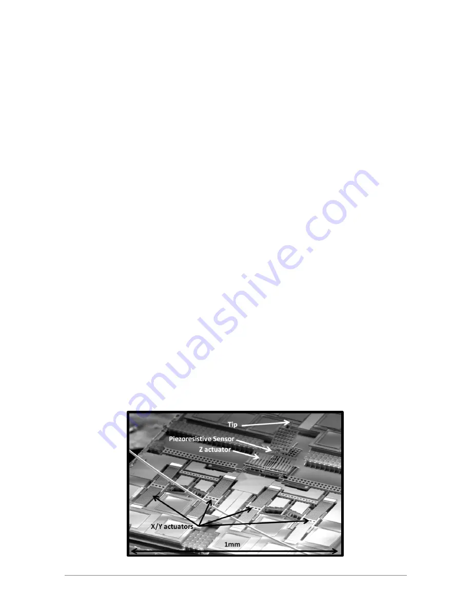
MEMS AFM or AFM-on-a-chip operates almost exactly like a conventional AFM except that all
of the essential components are integrated onto a single chip. The nGauge AFM chip is a micro
-electro-mechanical systems (MEMS) device that uses the most advanced manufacturing
process in the world to produce tiny, ultra-precise scanners and sensors on a 1 mm x 1 mm
silicon chip.
An AFM on a chip has a cantilever and a sharp tip but instead of a laser it has an integrated
piezoresistive strain sensor to measure tip displacements. The tip and sensor are attached to a
MEMS scanner that can position them in X, Y, and Z with sub-nanometer resolution.


